Still needs to be fully updated from Feather to KB2040 #
Reference documents #
Adafruit Feather RP2040 complete guide
Adafruit KB2040 hardware overview #
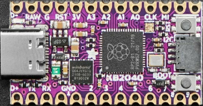
Looking at the picture above, you can see 2 large chips, some connectors, and a lot of tiny resistors and capacitors.
The chip just to the right of center is the microcontroller that acts as the brain of the board. It’s an RP2040 chip, which has dual ARM Cortex M0+ cores running at 133 MHz. The 20/43 code on the chip means that this particular chip it was manufactured in week 43 of 2020. The RP means that it is made by Raspberry Pi.
The square chip closer to the upper right corner of the board is the Flash memory chip for storing files and code.
Adafruit provides a handy overview of all the Feather RP2040 components and pins.
Why are there no header pins? #
The Feather is shipped without header pins to keep costs low and to give users options for how they attach sensors and actuators to it. Users can decide whether and which header pins to solder to the Feather PCB.
In ME 30, you’ll want to be able to plug your Feather into a breadboard for stability and wiring. Find the header pins that are enclosed with your Feather, and solder them onto the Feather PCB. Before you do this, check out Adafruit’s Feather soldering tutorial: https://learn.adafruit.com/how-to-solder-headers/male-headers
Connectors #
The board has three different connectors. On the left of the board is a USB-C connector used for power and data. You’ll connect to your computer through USB-C to install CircuitPython on your Feather and to edit code. The black connector on the top left of the board is a JST connector for a 4.2/3.7V lithium polymer (LiPo) or lithium ion (LiIon) battery. If your Feather is powered by USB and has a battery attached to this port, it will re-charge the battery. On the right edge of the board is a STEMMA QT connector, which allows you to connect I2C sensors and breakout boards to the Feather.
Buttons #
You’ll notice two small black buttons encased in silver boxes. The BOOTSEL button is used when you install or update CircuitPython on your Feather (press and hold BOOTSEL while plugging the board into USB or pressing RESET). The RESET button resets the board without disconnecting it from power.
LEDs #
The Feather has three built-in LEDs. On the left edge of the board, above and below the USB-C connector, are two small LEDs.
The one labeled 13 is a red LED connected to pin D13. You can easily turn it on and off in CircuitPython code using the variable board.LED. It also indicates bootloader mode by pulsing.
The LED labled CHG indicates the charge status of a connected battery. If no battery is in place, this LED might flicker as the charge circuitry tries to detect whether there is a batter or not.
The NeoPixel LED indicates the runtime status of CircuitPython code. It can also be programmed to glow in difference colors using the variable board.NEOPIXEL and the code in the NeoPixel library.
Quirks #
To be added as we encounter them (e.g., current limits per pin; serial port delay) #
Learning to program your Feather #
Check out this website’s Feather programming notes.
Adafruit’s CircuitPython Tutorials are a great resource for newcomers to the world of microcontrollers.