If we’re thinking about electricity like it’s water flowing in a pipe, then a resistor is like a narrow restriction in a pipe that limits the amount of current that can flow through.
Here’s what resistors actually look like in the real world.
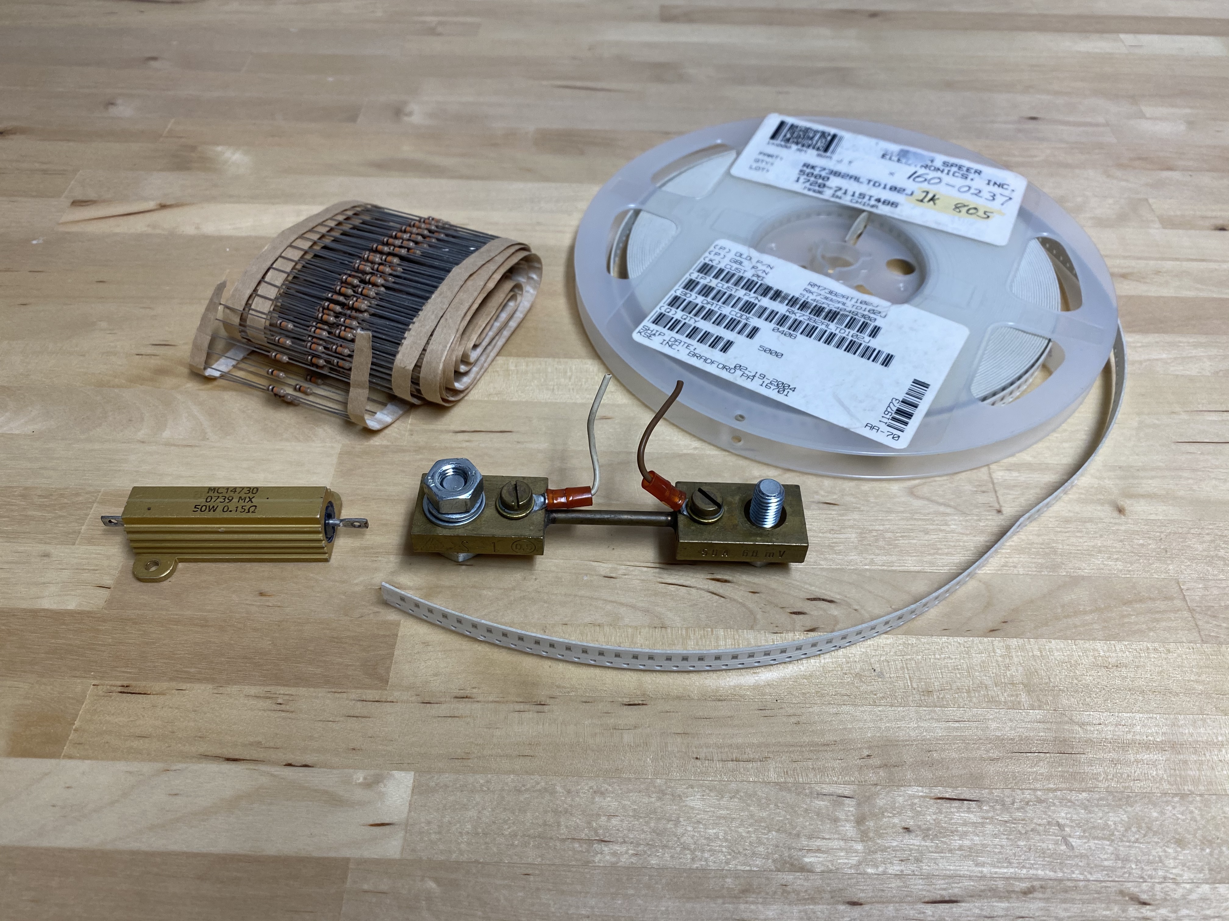
At the top left, we have 1/4 W, 10k carbon film through-hole resistors. They’re probably the most common resistors in the world.
At top right, we have a big spool of 1/10 W, 1k surface-mount resistors. They might rival the carbon film resistors at left for the popularity title.
The big blocky brass thing in the middle is a current shunt, that is, a resistor that has a very low resistance that is precisely calibrated. You run a large current through the rod in the middle, and then you measure the voltage drop with the two wires on either side. If you look carefully at the right hand side of the shunt, you can seea legend stamped into the metal that reads, “50 A 60 mV.” This means that when you measure a 60 mV drop across the shunt, 50 A is flowing through it. (Thus, its resistance is 0.060/50 = 0.0012 ohms, or 1.2 milliohms.)
In the lower left, we have a power resistor. This is just a resistor encased in a big block of metal so you can run a lot of current through it without melting it. The last line of the legend printed on it says, “50W 0.15Ω,” which means that the resistor can dissipate 50 W without burning up. Knowing its power limit and resistance, you can calculate its current and voltage limits: sqrt(50/0.15) = 18 A, and sqrt(50 * 0.15) = 2.7 V.
Resistors are linear #
When we say something behaves linearly, we just mean that if you double the input, the output also doubles. If you triple the input, the output triples. With a resistor, if you double the voltage pushing electrons through the resistor, the current through the resistor will double.
In reality, resistors aren’t exactly linear, but they’re close enough. The most common deviation that you’ll run into is that as you run more current through a carbon film resistor, it heats up. As it heats up, the resistance drops slightly, so if you double the voltage, you actually get slightly more than double the current. (But that’s just carbon film resistors. The resistance of copper wires is just the opposite– it increases slightly with temperature.)
We measure resistance in ohms #
We measure resistance in ohms ( \(\Omega\) ), a measure of how many amps the resistor lets through per volt applied to it. A 1 ohm resistor lets through 1 amp per volt.
This brings us to Ohm’s Law, which is really just the definition of resistance as the ratio of voltage applied to current passed. You could write it as
\(V / I = R\)but it’s more commonly written as
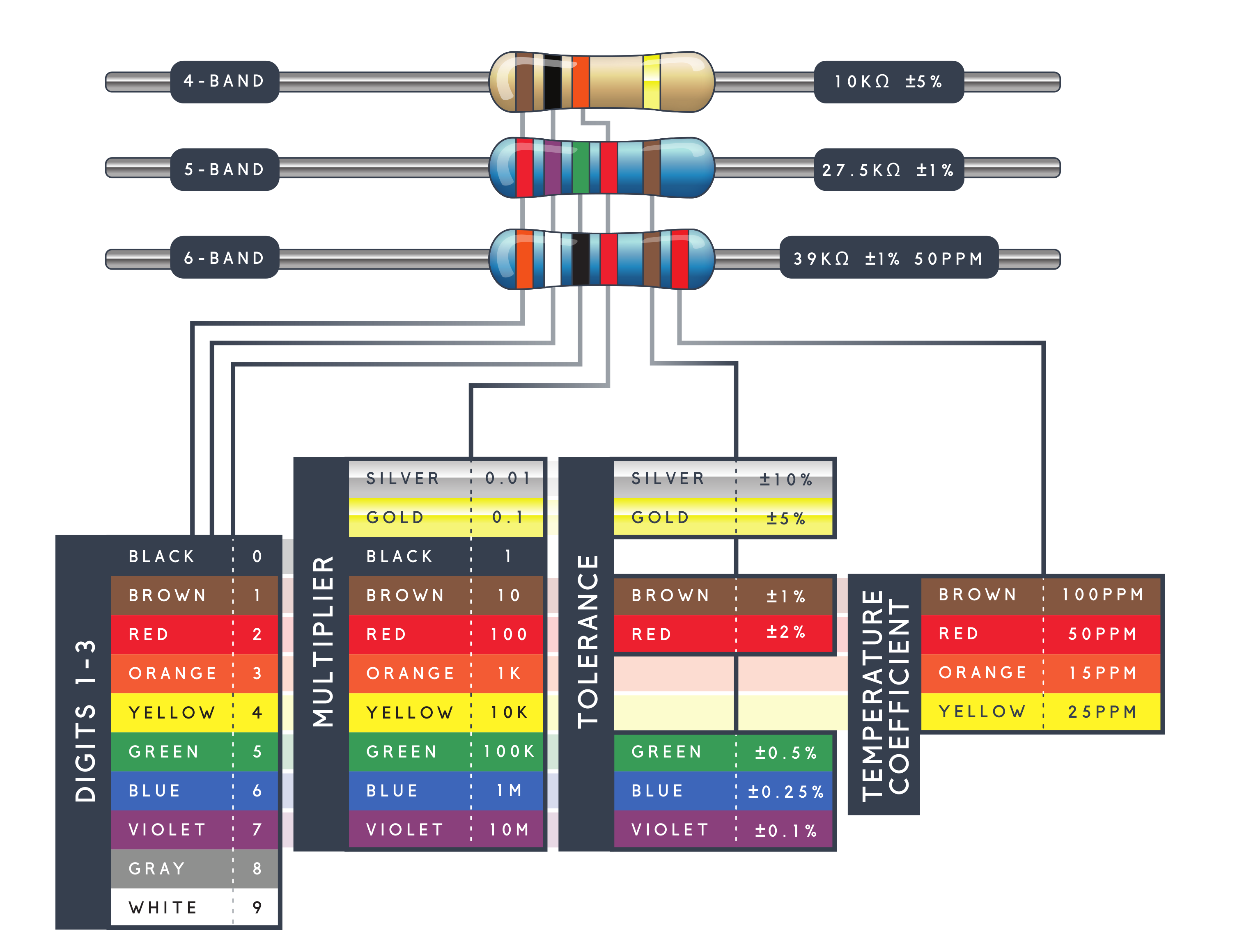
\(V = IR\)The pattern of color bands on a through-hole resistor tells you its resistance value. Here’s a guide to resistance color bands.
Power rating #
One other matter to worry about is what happens if you run a lot of current through a resistor. Raise the current enough, and the resistor will eventually burn out.
We can calculate power by multiplying voltage and current. Think this through with the meaning of the units: volts are joules per coulomb, and amps are coulombs per second. In the product of the two, the coulombs cancel, so we get joules per second, as we would expect for power, a measure of the rate of energy flow.
Typical carbon film resistors are rated for 1/4 W. Typical 0805 surface mount resistors are rated for 1/8 W.
Tolerance #
When resistors are manufactured, there is some variation in their resistance. Typical cheap carbon film resistors are specified to be accurate within 5% of their nominal value, but they are usually closer than 1%. This is different than capacitors, which are specified to be within 10% or 20% of their rated value, and often push those limits, especially across signals of different frequencies. You can pay more money to get resistors with tighter tolerances.
Typical application: current limiter #
LEDs have the unusual characteristic that they start emitting light when you hit a certain voltage threshold, called \(V_f\) for “forward voltage”. Curiously, it varies with the color of the LED. If you try to raise the voltage across the LED above \(V_f\) , it just gets brighter and hotter until it burns out. Unfortunately, the voltage threshold is not a convenient voltage like 5 V; it’s something weird like 2.9 V or 3.1 V. To run an LED from a microcontroller, which usually has a fixed output voltage, the usual strategy is to put the LED in series with a resistor that allows the LED to reach its threshold voltage while limiting the current to a level where the light emission is pleasant.
The usual calculation for a 5 V system goes like this:
\(5 - V_f = V_R\)1 mA is a good place to start with a 5 mm LED, so we can plug \(V_R\) in to Ohm’s Law.
\(V_R / 0.001 = R\)Typical application: voltage divider #
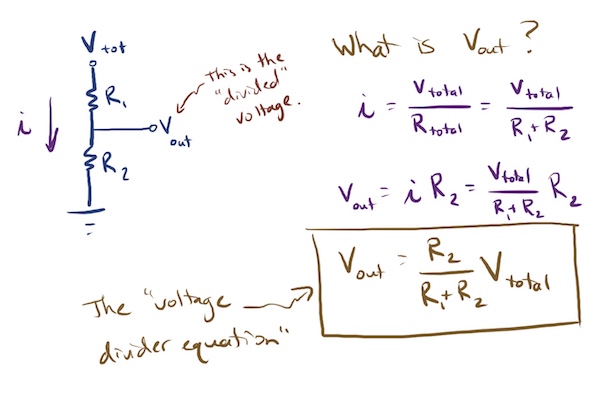
A voltage divider is merely two resistors stacked in series. As current flows through the resistors, the voltage drops in proportion to the fraction of the total resistance passed through.
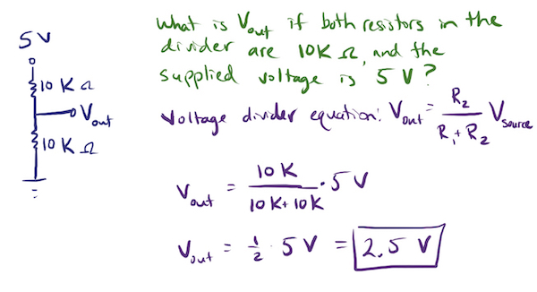
If you have, say, two 10k resistors stacked with 5 V applied, the voltage at the point between them will be 2.5 V.
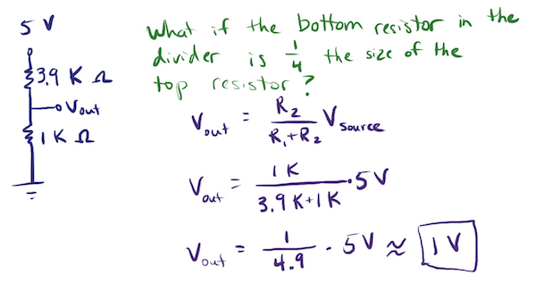
If you have, say, a 3.9k and a 1k resistor stacked with 5 V applied, the voltage at the point between them will be around 1 V.
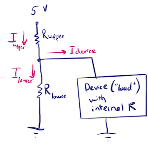
You might think that all that matters about a voltage divider is the ratio of the two resistors. Usually, you would be right. But, the purpose of the voltage divider is often to supply a reference voltage to another device. If that device draws off some current, the voltage between the resistors will start to sag, because less current is flowing through the lower resistor. To prevent this, make sure that the current drawn off into your device is at least 100x less than the current flowing through the divider itself. Alternatively, if the sag is predictable, you could just set the divider a little higher and let it sag to the original target.
Typical application: pull-up or pull-down #
With microcontrollers and MOSFETs, you often have pins that you want to tie to a certain voltage. For example, most microcontrollers have a reset pin; when you apply 0 V to the pin, the microcontroller is reset. Here’s a convenient circuit for that situation.
In this situation, the resistor is called a pull-up resistor, because it pulls the voltage on the pin up to 5 V. If it were connected to ground instead of 5 V, it would be called a pull-down resistor.
Because of the circuitry inside the microcontroller, very little current flows into the reset pin. This means that very little current flows across the resistor, so there is very little voltage drop across it, so the reset pin is held near 5 V. When you press the pushbutton, the reset pin is pulled to ground, and the reset occurs. While the button is held down current flows through the resistor, through the button to ground.
You might think to yourself, “But couldn’t the resistor just be a wire?” If the resistor were a wire, it would still pull the reset line high just fine, but when you pressed the pushbutton, you would be shorting 5 V to ground. Don’t do that.
Guide to resistance color bands #
Determine the resistance using this guide.