The H-bridge motor driver #
What is an H-bridge and why would I want one? #
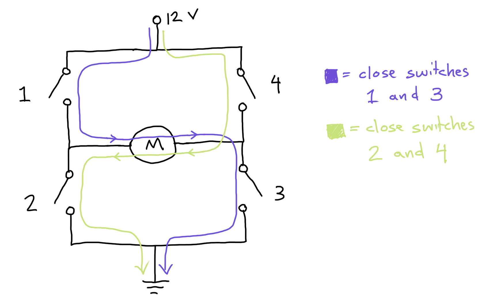
An H-bridge is a simple, commonly used circuit that can make motors spin in both directions. When you draw a schematic of the circuit, it looks kind of like the letter H, with the motor bridging the two sides of the circuit.
Conceptually, the circuit consists of 4 switches. When they’re all off, the motor is stopped. When you turn on the upper left and lower right, current flows one way, and the motor spins. When you turn on the upper right and lower left, current flows the other way, so the motor reverses.
For small, low-power motors, you can get chips that contain all 4 switches in a single package. As motors get bigger, we start using 4 separate MOSFETs for the 4 switches. In ME 30, we’re going to build an H-bridge using 4 separate MOSFETs, because that’s what we can prototype on a breadboard.
What kind of MOSFETs do we use? #
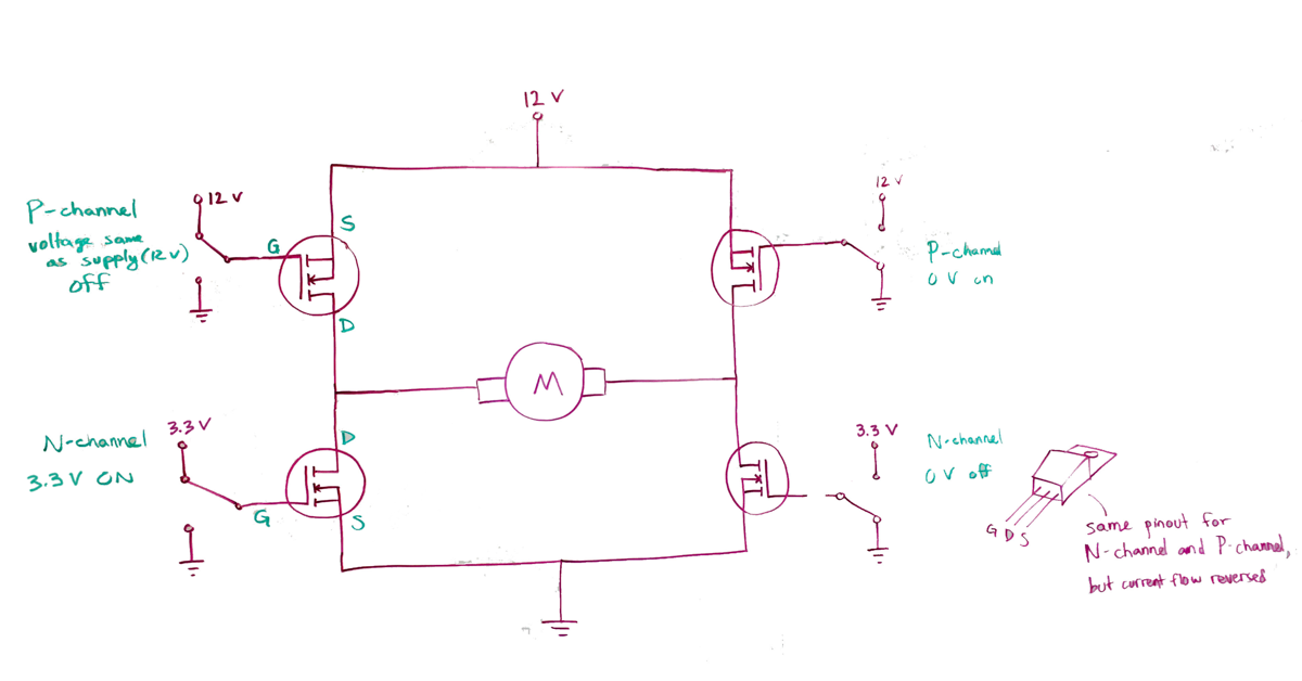
Typically, the lower two MOSFETs in the circuit are N-channel MOSFETs, while the upper two are P-channel. (If the upper ones were N-channel, you would need a higher gate voltage to turn them on, which is inconvenient.) A good starting point would be the IRLB8721 MOSFET for the N-channels and the FQP27P06 MOSFET for the P-channels. Both MOSFETs are cheap (around $0.80 from a US distributor) and widely available. They can handle 25-30 A when on and withstand 60 V when off.
Don’t I still need high voltage to turn off the P-channels? #
Yes, you do. The trick that people use is to a low power NPN bipolar junction transistor, like the 2N3904, to turn on the P-channels, and then a pull-up resistor to turn them off. Then you can control the P-channels through the BJT’s using 3.3 V or 5 V logic signals from a microcontroller.
-
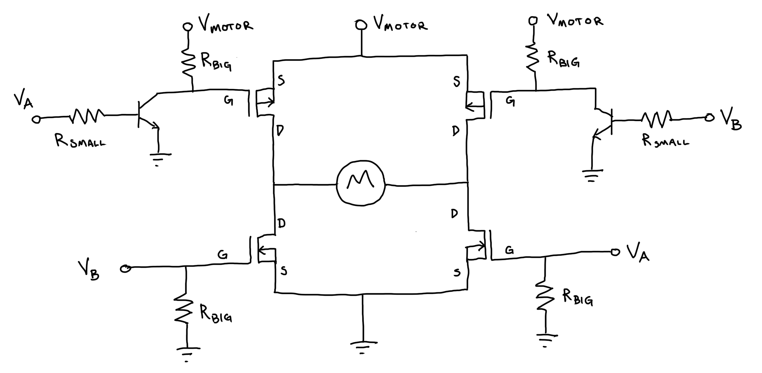
V_motor is the higher voltage needed for the motor to run. This semester we’ve been using 12 V.
-
V_A and V_B are either 0 V or the low voltage (typically 3.3 V or 5 V) needed to switch on the transistor. These voltages are usually sent out by a microcontroller. At least one these voltages must always be 0 V. Never allow V_A and V_B to have positive voltage at the same time!
But if we have to use a BJT, why not use that instead of the MOSFET? Why both? #
The 2N3904 costs around $0.01, i.e. it is approximately free, but it can only handle around 0.5 A. You could instead get a larger power transistor. In some circumstances, people do that, but H-bridges tend to be pulsed on and off very quickly (hundreds or thousands of times per second) for speed control. MOSFETs require much less energy to turn on and off than BJTs, so the MOSFETs make the circuit more efficient. At really high currents (hundreds of amps, say for an electric car), people switch from MOSFETs to a weird hybrid of the two called an insulated gate bipolar transistor. IGBT’s are cool, but they’re also more expensive. Stick with the MOSFETs for now.
What are RBIG and RSMALL? #
RBIG is a pull-up or pull-down resistor. With the upper MOSFETs, its job is to fill the capacitor in the MOSFET when you turn off the BJT. This turns off the P-channel MOSFET. With the lower MOSFETs, its job is to drain the MOSFET capacitance whenever your control lines are not connected to anything. The idea is to keep your motor from spinning wildly while your microcontroller is booting up. For both pull-ups and pull-downs, the exact value is not very important– values of 10k or 100k are typical. We use these large resistance values so that the current draw - and thus the energy consumption and heat generated - remains small through these branches of the circuit.
RSMALL is a current-limiting resistor for the BJT. When the BJT is on, the base voltage is around 0.6 V, so if you’re driving the resistor with a 3.3 V microcontroller, a 1k resistor would allow around 3 mA to flow. It would probably still work with a 10k, or even a 100k, since the MOSFET needs so little current to drain its capacitor, but 1k is probably a better choice. Less than 1k might work, but you might overload your microcontroller’s output pin.
Prototyping an H-bridge motor controller circuit #
In your ME 30 kit, you’ve got everything you need to build an H-bridge circuit on a breadboard. If you’re totally unsure of how to get started, study the diagrams on this page. For ideas about how to test and debug your H-bridge systematically, check out the Testing an H-bridge half demo video.
Pathologies and debugging #
- Motor was pulsing, because power supply was overloaded, because P-channel was shorted to ground, because circuit design was misunderstood.
- BJT exploded. Visual inspection revealed missing chunk.
- Did not understand building blocks of circuit before using to build larger system.
- Smoke coming out of transistor. Replaced transistor.
- Components getting hot. Tested parts in isolation to get each part working.
- Visual tracing of wires to match wires to circuit design.
- Incorrect understanding of pinouts and part numbers from datasheets.
- Difficulty packing components together to make PCB small.