Projects 5 and 6: Build an intrepid robot that cooperates with another robot to balance two payloads #
Projects 5 and 6 are, in a sense, one mega-project. In the first part, P5, you and your team build a robot. In the second part, P6, you and your team modify the robot to deliver a payload under specific diabolical constraints.
Requirements for project 6 #
With another robot, measure and balance two payloads #
Due date: during your choice of the ME 30 final exam blocks (see Calendar)
For the final project of ME 30, your task is to modify your robot so that it can measure the mass of the payload from P5. Once it measures the mass of the payload, it should deliver the payload to a wisely chosen location on a seesaw.
The payloads #
There are 3 different kinds of payloads. From the outside, they all look the same. However, they have masses of 400 g, 700 g, or 1000 g. The payload masses are accurate to within 1%.
(Please do not make distinguishing marks on the payloads; the point is that you are supposed to tell the difference between them using the load cell on your robot’s arm.)
The seesaw #
The seesaw is marked with measurements showing the distance from the central pivot. Once you know how much your payload weighs, your robot should deliver it to the seesaw. Another team will deliver a payload to the other side of the seesaw at the same time. Once both payloads have been delivered, the stops on the seesaw will be released. If your robots have measured the payloads correctly and placed them prudently such that the torques balance, the seesaw will balance. If one or both of the robots have placed them poorly, or mismeasured the payloads, the seesaw will tilt, dumping the payload into the void, chased only by your sorrows.
A few more details #
- The center of the seesaw is off limits. (Otherwise, you could trivially solve the problem by placing both payloads at the center.)
- The payload you have to balance will be chosen at random.
- Your robot can work with any other robot. (If your robot works well, please consider running again with a few other robots.)
- If your robot fails at first, you can try again.
- You can choose when you want the seesaw stops released, but both stops must be released at the same time.
- You can reposition your payload if your robot can manage to do that.
Requirements for project 5 #
Build an intrepid robot that can carry a hefty payload #
Due date: Tuesday, December 2, 11:59 PM
This is a relatively constrained project compared to the vast open field of P4. Your task is to build a robot that can drive on level surfaces while carrying a payload, controlled remotely by you.
- Your robot should fit in a circle 45 cm in diameter.
- Your robot should be less than 45 cm tall.
- Your robot should be able to carry a hefty payload, as shown in the diagram below. By Project 6, your robot will need to be able to lift the payload on its own, high enough to carry it.
- Your robot should still be able to maneuver while carrying the payload. Specifically, it should not tip over.
- This is a tricky requirement: for P6, your robot will need to measure the mass of the payload it is carrying, using a load cell. For P5, you need only to include the load cell in your lifting mechanism; you don’t have to connect it yet. (And for P5 it’s okay if your lifting mechanism isn’t working yet. You can place the payload manually on your robot arm.)
- You should not touch your robot during its adventures. This probably means that your robot should be remote controlled.
- You should not use an RC car controller. This probably means that your robot should be controlled through wifi to your Raspberry Pi from a laptop or phone.
- Your robot cannot fly. (We don’t have the space to test drones safely, unfortunately.)
- Note: It would be a good idea to focus on making your robot drive effectively before you worry about any higher level mechanics or control through the internet.
Here’s the environment in which your robot will be operating. It will be constructed in Nolop.

Payload specifications #
- Maximum weight: 1 kg +/-10%
- CAD model of the payload available here: https://cad.onshape.com/documents/dc378c67d38d4fa845a7e22c/w/e9e96efc287cc2ab77fdccee/e/9c0f0d79fea43c7bbd834401?renderMode=0&uiState=6916591057b57914d88f4236
By the due date, your team should video-record your robot doing a test drive on a basic course set up in Nolop: drive up to a loading dock, place the payload on your arm, and drive to another loading dock. If your robot meets the requirements above, it will do fine. The payload and a loading dock will be available in Nolop for testing.
Materials each team will be given #
- A load cell (actually, one per team member, but you only need one) (see our Sensor Amplification page to learn how to use it)
- A steel bar, approximately 12.5 x 3.2 x 460 mm, easily stiff enough to carry the payload, with a little hook in the end
Project planning resource: We suggest discussing this list of P5 planning questions with your team.
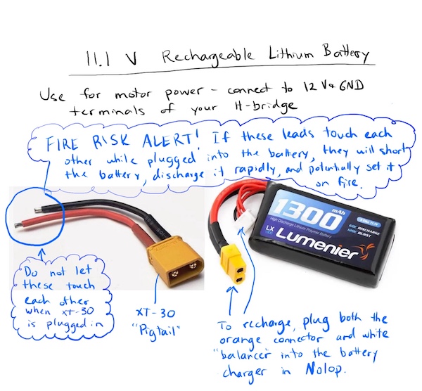
Batteries for projects 5 and 6 #
For portable power, Nolop has 5 V batteries (for the Raspberry Pis) and 9 V and 11 V batteries (for motors). For motors, you can also forego the batteries and use an extension cord to your 12 V power adapter.
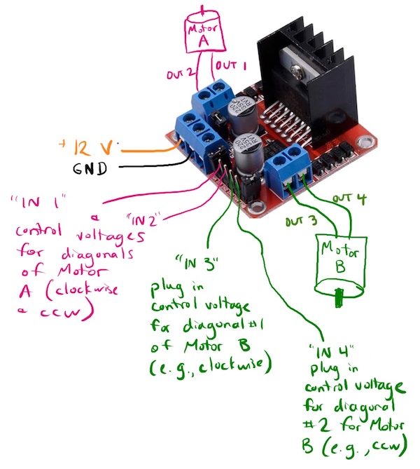
H-bridges for projects 5 and 6 #
The goal is for you to use your Project 3 H-bridge PCBs for your robot motor control. However, as a last resort, if no one on your team can get their P3 PCBs to work, you can find a dual-H-bridge PCB (called an L298N motor driver) in the Nolop store.
Please see the sketch below for details on how to wire the L298N dual H-bridge board.
More details for projects 5 and 6 #
- See the Raspberry Pi setup page to learn how to control your Pi via serial cable and the Internet.
- See the Raspberry Pi programming page for snippets of Python code to control the pins on your Pi.
- See the servers and clients page to learn how to coax your Pi into sending and receiving data through the Internet.
- See the web page buttons section to see how to make a web page with buttons that send HTTP requests.
- See the Internet page to find out how IP addresses work.
Team options for projects 5 and 6 #
Option 1 – Work in a team of 2 or 3 chosen by you
Option 2 – Work in a team of 2 or 3 assigned to you by instructors We’ll pool all the people who would like to be assigned a partner and team you up. We might need to make a team of 3 depending on who is available.
Use this survey to indicate your chosen teaming option (list your teammates or indicate you’d like to be placed on a team).
Project 4: Build an electromechanical game #
Your task is to build a game with the following characteristics:
- It is controlled by a KB2040 microcontroller.
- It uses your H-bridge prototype to drive a motor in at least one direction. (If you need a second H-bridge, you can make another one or use any motor driver that will work.)
- It has some kind of user input, like a button, knob, joystick, sensor, or the like, that talks to the KB2040 microcontroller. (Read the note below about the ME 30 Nolop tab).
- It has at least one part that moves, driven by one of the motors in your kit. (You can use both motors if you want. Servo motors are prohibited.)
- It is at least sort of fun to play. A blinking LED is not a game.
- It includes no 3D printed components whose STL files were downloaded from the internet.
- Its major structural components are NOT 3D printed.
Personal learning goals #
As soon as you can manage it, you should formulate and submit to Canvas one or more personal learning goals for the project. Building games is cool, but the real point here is for you to gain skills and experience that help you grow as an engineer. That works best when your heart is in it; this is your chance to follow where your heart leads. (Okay, that’s a bit cheesy, but also true.)
By Wednesday, October 29, 11:59 PM, please describe your learning goal on Canvas.
At the end of the project, one of the reflection questions will ask you whether you met your learning goal.
Where to get materials for your game #
To build the game, you can use anything from your ME 30 kit, as well as anything else you can lay your hands on. Additionally, Nolop has buttons, potentiometers, LEDs, and other electronic components, as well as materials for laser cutting. You can use Nolop materials for your projects by recording them on the ME 30 tab located on a clipboard on top of the Nolop store. (At the end of the semester, the ME department pays Nolop back for all the parts we use.)
Bray also has materials for fabrication, leaning more toward the metal/nuts/bolts end of the spectrum.
If you need something not available at Nolop or Bray, please talk to Brandon, Zosia, or Kristen as soon as you can.
Due date for game: Wednesday, November 12, IN CLASS
Documentation due on Canvas by Wednesday, November 12, 11:59 PM
On November 12th, class will consist of us playing each other’s games, marveling at our collective ingenuity and resourcefulness, and introducing Project 5.
Project 3: H-bridge #
Build an H-bridge motor controller
The third project is to build a motor controller to meet the following requirements:
- It consists of a PCB with connectors for a motor, plus power and control lines.
- It also accepts power from a 2.1 x 5.5 mm plug from a 12 V wall adapter.
- It has a power LED that lights up when motor power is available.
- It can make a DC motor spin in both directions.
- The motor current traces can handle 12 V and 5 A continuously without melting (see notes on PCB ampacity)
- It can be controlled by logic signals from a KB2040.
Here is a graphical version of those first two bullet points about connectors.
Due date for prototype: Monday, October 20, 11:59 PM
To get started building your prototype H-bridge, review the Low Power/high power and the H-bridge(http://andnowforelectronics.com/notes/h-bridges/) pages, including their mini-lecture videos on BJT and MOSFET transistors. After that, if you’re stuck, consult the H-bridge testing demo video. Note that this video is not intended to give you step-by-step building or testing instructions, but rather to give you a feel for the kind of approach you might take to building and testing this circuit. If your H-bridge prototype isn’t working by the deadline for this prototype, don’t worry! Just submit to Canvas a photo of what you have, working or not.
However, once you do get your breadboard H-bridge working, take a video that shows it making the motor spin in both directions, controlled by a KB2040. You’ll need that video eventually for your P3 final Canvas submission.
Due date for functional breadboard H-bridge and PCB submission: Monday, October 27, 11:59 PM
When your PCB design is ready, you should submit it to the fabricator, OSH Park. If you focus on compact design, you can keep the cost to around $10. (If this cost is a hardship, please tell your ME 30 instructor or Courtney Russon in the ME office, and we will cover the cost by ordering it for you, no questions asked.) After you order it, take a screenshot of your order confirmation (proof that you submitted your project on time). Also, take screenshots of your circuit layout and PCB design in KiCad (it would be a good idea to save these screenshots for your portfolio). Upload all your screenshots to Canvas.
For this final submission to Canvas, you will also need to submit evidence that your breadboard H-bridge circuit is functional – a video that shows it making the motor spin in both directions, controlled by a KB2040.
Project 2: Simple game #
Build a simple game
The next project is to use the basic electrical components we’ve covered in class with some mechanical fabrication to make a game that is at least mildly entertaining. The point here is NOT making the best game ever, but to set some goals for testing out your electromechanical skills. For your circuit for this project, use your breadboard. No PCBs needed.
This is a solo project, but we’ll be brainstorming in groups.
You should bring your game to class on Wednesday, October 8th to share with your brainstorming group.
Due date (for game documentation submission): Wednesday, October 8th, 11:59PM
To keep things simple, there are a few required constraints. Your game should:
- Use the DC gearmotor in your kit
- Use at least one transistor from your kit (can be a BJT or MOSFET)
- Require user interaction of some sort (e.g., pushing a button, pressing a key, interacting with a physical component)
- Fit inside a cube 20 cm on a side
- Be fabricated without 3D printing, except for a motor hub if needed (talk to an instructor if you have a particular reason you need to violate this constraint.)
The point of the constraints is to keep your game simple enough that you can complete it in 1.5 weeks.
In addition to planning to meet these constraints, you should also pick one learning goal for yourself for this project. Open-ended projects offer you an opportunity to bend the curriculum into the direction of your interests or to explore a potential new area of interest.
Here are some example learning goals:
- Get more comfortable with cordless drills and at least one other hand tool.
- Test my system to failure, then rebuild it stronger.
- Use only recycled/found materials.
- Complete my project 24 hours early.
- Model, predict and subsequently measure at least one mechanical property of my project.
- Use the laser cutter (which I have never used before).
- Make at least one part out of steel.
- Turn a part on a lathe at Bray.
- Spend at least 1/3 of my effort on the aesthetics of the project.
Project 1: Power supply #
Build a breadboard power supply
The first project is to build a power supply that meets the following requirements:
- It consists of a PCB that plugs directly into a breadboard.
- It accepts power from a 2.1 x 5.5 mm plug from a 12 V wall adapter.
- It emits 12 V, 5 V, and 3.3 V (at the same time).
Due date for Printed Circuit Board submission: Wednesday, September 24, 6:00PM
Due date for prototype on breadboard: Monday, September 15, 11:59PM
When your design is ready, you should submit it to the fabricator, OSH Park. It will cost you around $10. After you submit it, take a screenshot of your order confirmation. You’ll need to upload it to the Project 1 PCB assignment on Canvas. That will serve as proof that you submitted your project on time. If this cost is a hardship, please email your KiCad files to your ME 30 instructor, and we will order it for you.
More details for Project 1 #
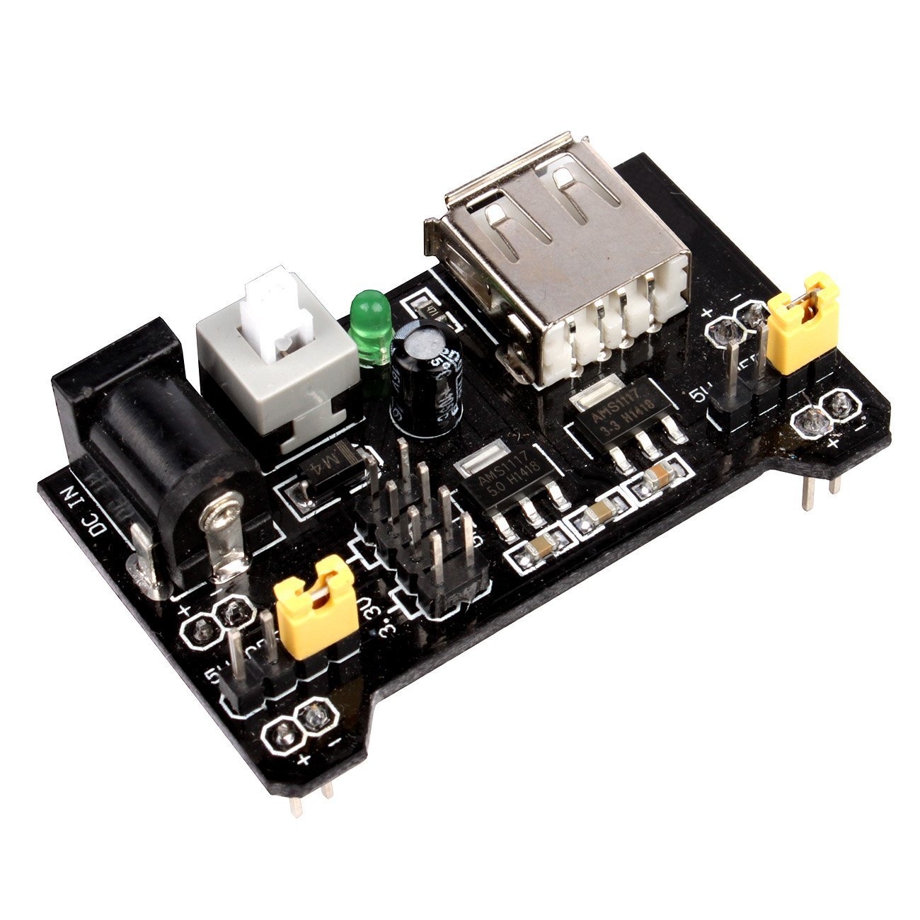
First of all, we’re not trying to build anything revolutionary in this project. None of you have ever made a PCB before, so the point is to make something fairly simple to get comfortable with the process. If you search Amazon for “breadboard power supply”, you’ll see that you can buy various versions of things like this, though none with a 12 V passthrough, so far as we’re aware.
Here’s what a typical one of these things looks like.
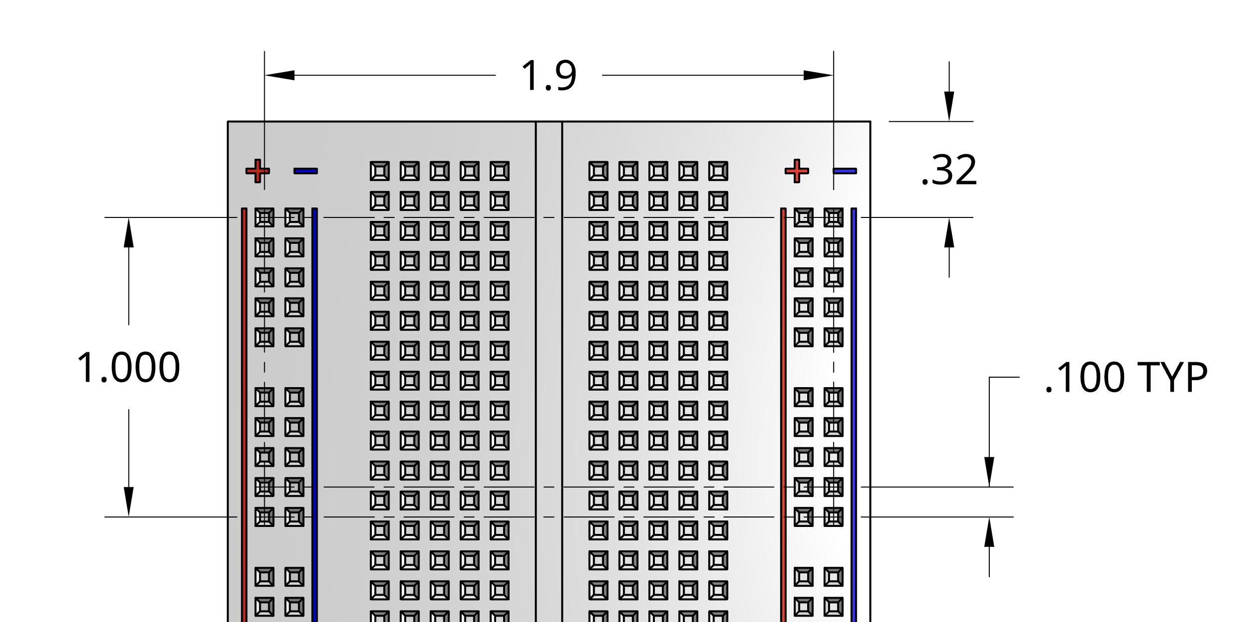
The image below shows the mechanical constraints for the PCB. You can make a board of whatever dimensions you want, but it needs to plug into the breadboard, so you probably want to make sure that the pins line up with the holes in the breadboard, as shown below. You can get by with 4 pins, but 8 will make the board stay in place a little more securely. Regardless of how many pins you use, make sure that each rail has only matching pins, i. e. don’t accidentally connect 5 V to GND.
The dimension between the outer pins is estimated at 1.9 inches. It would be a really good idea to verify that dimension on your breadboard. Sometimes the breadboards are a little wider or narrower.
You can rely on the rest of the dimensions being quite accurate.
In your project kit, you’ll find all the components you’ll need to build a prototype of your power supply on a breadboard. You build the prototype and make sure that you’ve got the wiring right. Then, make the PCB with the same connections. Finally, when your PCB arrives in the mail, you can reuse the prototype components on your PCB.
Important note: the pins on the 5V and 3.3V regulators are not in the same order!
Check the datasheets for the components to see which pin is the input pin, which is the output pin, and which should connect to ground.
If you feel like you understand this project pretty well, or if you’ve made a basic circuitboard before, you could try adding additional features. Look at the open source Ant breadboard power supply for inspiration. The schematics are available if you’re curious about the details.
P1 prototype: what you should try before class #4 (photo of prototype due to Canvas 11:59pm, Wed., 9/15) #
- Read and try to make sense of the website notes on voltage regulation. Pay special attention to the circuit diagram showing the L7805C voltage regulator.
- Try your best to make a breadboard circuit so that 12 V goes into your circuit and 5 V and 3.3 V come out. To get started, see the schematic on the Voltage Regulators web page. You’ll need to use your 5V and 3.3V voltage regulator components.
- Read as much of chapter 2 from the Practical Electronics textbook as you can.
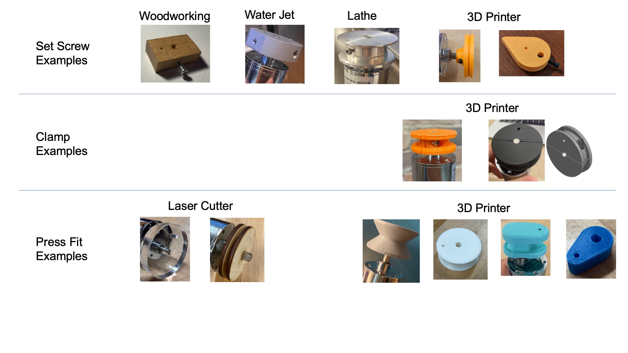
Project 0: Motor hub #
Create a secure motor attachment
Later this semester, Projects 2 and 4 will require using a motor to actuate some part of an interactive game, and Projects 5 and 6 will involve motor-driven wheels. So in Project 0, you’ll building some knowledge about how to attach a part securely to a motor.
Your task in Project 0 is to design and build a motor hub that meets the following requirements:
- It fits on and attaches to your DC motor shaft
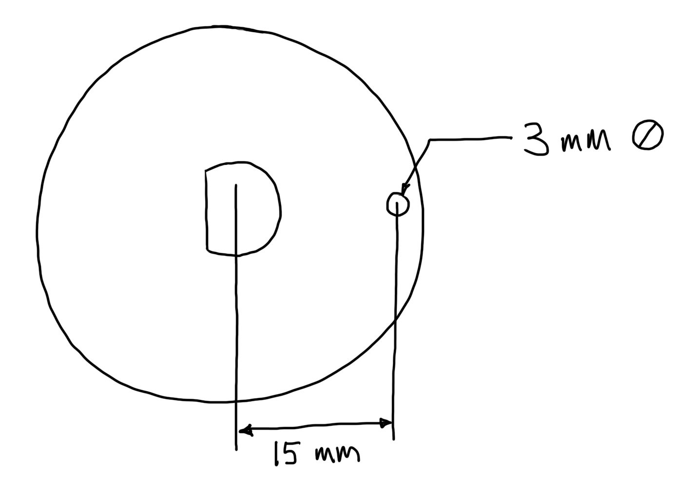
- It includes a 3 mm hole located 15 mm from the central axis of your DC motor shaft (you’ll insert a paper clip with a weighted string into this hole)
- Around its circumference, it includes a channel or groove for winding up 1 meter of string
- It stays attached securely enough to handle the amount of torque (load applied to hub) that stalls the motor when it is operating at 12 V
Your motor hub can be shaped however you like as long as it meets these requirements; the details are up to you.
Submit to Canvas (1) a photo of your motor hub and (2) a brief video (max 90 seconds) demonstrating that your motor hub meets the requirements above.
Bring your hub to lab on your designated due date. We hope to compile everyone’s results indicating the range of torques applied before the hubs either (a) slip on their motor shaft or (b) successfully stall the motor.
Due dates are staggered for Project 0 to spread out the demand on fabrication tools at Nolop and Bray. Your hub is due at the start of lab time on the date listed for your weekly lab day.
| Your Weekly Lab Day | Your Project 0 Due Date |
|---|---|
| Wednesday | Wed., Oct. 1 |
| Thursday | Thurs., Oct. 2 |
| Friday | Fri., Oct. 3 |
| Sunday | Sun., Oct. 5 |
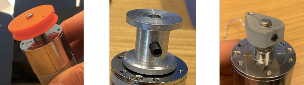
Prior Student Examples NOTE: Not all of these examples meet the requirement of a channel or groove for the string to travel - that’s new for 2025!