Why do we need voltage regulators? #
(Make sure you understand the difference between voltage and current, or this won’t make any sense. Also, remember that power = voltage * current.)
Suppose, as an example, you want to make your own toaster oven. You’ve done some heat transfer calculations, and you think you want the electric heaters in your oven to deliver around 1500 W.
Here are two ways you could do it.
Low current approach #
You could get a 150 V power supply that can supply at least 10 A and connect it to a heater with a resistance of 15 ohms. 150/15 = 10, so 10 A would flow. 150 * 10 = 1500, so you would be delivering 1500 W.
High current approach #
You could also get a 15 V power supply that can supply at least 100 A and connect it to a heater with a resistance of 0.15 ohms. 15/0.15 = 100, so 100 A would flow. 15 * 100 = 1500, so once again you would be delivering 1500 W.
So, is there any difference?
It turns out that there’s actually a major difference. Suppose you connected the two ends of your heater to your power supply with two wires like the ones in your project kit, but each 5 feet long. That’s 10 feet of 22 gauge wire in total, which has a resistance of around 0.16 ohms. In the high current approach, that’s roughly the same resistance as your heater.
That means that while you thought that you would get 100 A flowing, but you’ll really only get around half as much, because of the resistance of the wires in your power supply. What’s worse, half of the heat will be delivered to the wires, which are presumably outside of the toaster oven, so you actually only get 1/4 of the power you thought delivered to the oven itself. But it gets even worse– the 1500/4 = 375 W delivered to the wires may be enough to melt the insulation off and possibly start a fire. Oops.
A key figure to remember here is described by the phrase, “ohmic losses.” The power dissipated in a resistive element like a wire is \(P = VI\) , which is the same as \(P = (IR) * I\) or \(P = I^2R \) . The implication of this is that generally, when we’re building electronics, if we have a choice between high voltage and high current, we choose high voltage, especially when we’re trying to push a lot of energy across a long distance, as in overhead power lines.
Safety note
At voltages of 30 V or higher, you need to start being careful about not getting hurt. We will not be doing anything with voltages above 12 V in this class, but it’s still good to remember that your body is kind of like a 70k resistor, and 10 mA through your heart can kill you.
Voltage regulation #
Okay, so we have high voltages because we want to avoid losing all of our energy in the wires leading to our devices. However, we don’t want to use really high voltage for everything– our motors would spin too fast and some chips might get too hot. How do we lower the voltage from a high voltage down to the one we want?
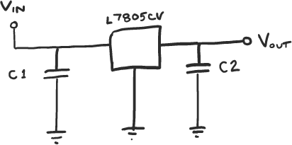
The easiest solution is to use a chip called a linear voltage regulator, along with two capacitors. A typical circuit is shown below. High voltage goes in one side, and low voltage comes out the other side. For the L7805CV that we use, the input voltage can range between 7 V and 25 V. The output voltage will always be very close to 5 V (maybe 4.9-5.1 V).
Linear voltage regulators have the disadvantage that they’re relatively inefficient (~50%), but they’re cheap, low noise, and simple to use. The other major option is to use a switching power supply, also known in the RC car world as a “Universal Battery Elimination Circuit,” or UBEC. Switchers are much more efficient (~85%), but they are also bigger, more expensive, and more complicated to build. Their rapid switching tends to leak electrical noise into the rest of your circuit, unlike a linear regulator.
What are the capacitors for? #
The capacitor on the input filters out fast changes in the input voltage, so they don’t ripple through to the output. If you omit it, and you have a noisy input, your regulator can start oscillating, get hot, and go into thermal shutdown.
The capacitor on the output helps the regulator stay more constant if whatever you attach to the regulator draws a bunch of current suddenly. It acts like a small battery that has to be depleted for the output voltage to change.
How does a linear regulator work inside? #
Each company that makes linear regulators has a different silicon die inside, but the architecture is roughly the same. There are three elements:
- A precise voltage reference that is below the output voltage. (In an adjustable linear regulator, like the LM317, you provide this reference outside the chip, thereby adjusting the output.)
- A transistor that acts like a variable resistor between the input and the output. This is where the inefficiency happens.
- An amplifier that compares the output voltage to the voltage reference. As different amounts of current are drawn from the output, the amplifier adjusts the transistor so that the output voltage stays constant, instead of sagging as more current is drawn.
These elements make up a basic control system. Hey, that’s what ME 31 is for! (You’ll study more interesting control systems than just voltage regulation, though.)