Common characteristics #
There are a few characteristics that virtually all motors share. Let’s go over those first; then we can discuss different variants.
First off, every motor has a part that spins, called the rotor and a part that stands still, called the stator. Usually, the rotor is in the middle of the motor, and the stator is around the outside, but there are also motors called “outrunners” where the outside rotates and the stator is fixed inside.
Power is the product of torque and speed, so for a given power level, to get more torque, you need to slow down. But, the efficiency of motors tends to drop with speed, so it’s usually wiser to run a motor at a high speed and then use a gearbox to drop the speed and increase the torque. You do lose a little energy to friction in the gearbox, but less than you would lose with a slower motor.
Usually, the limits of motor performance are thermal; if you drive too much current through a motor, the wire inside will get hot enough that its insulation will melt, which will create a short circuit. Then, lots of current will flow, and your motor will be destroyed. In general, the maximum torque you can get out of the motor before the insulation melts is roughly proportional to the volume of the motor. There are lots of different geometries– long, thin motors and short, wide motors– but if the volume is similar, the torque is similar.
Fundamental principle #
The fundamental principle of a motor is to run some electric current in a wire that is perpendicular to a magnetic field, which generates a force on the wire. If the wire is attached to a shaft mounted on bearings, that force acts as a torque, which spins the shaft. At this link is a great introductory video by Jared Owen showing in a conceptual, graphical way how a motor works. In the video below, Brandon demonstrates the ideas with a real motor extracted from a sander.
Motor types #
There are many kinds of motors, but let’s start with three comon types:
- a brushed DC gearmotor (you have this in your kit)
- a NEMA 17 stepper motor (you have one of these too)
- a hobby servo (you can get one of these at Nolop)
Each of these types of motors has lots of other variations, but these are good examples of the most common motors you’ll run into.
DC gearmotor #
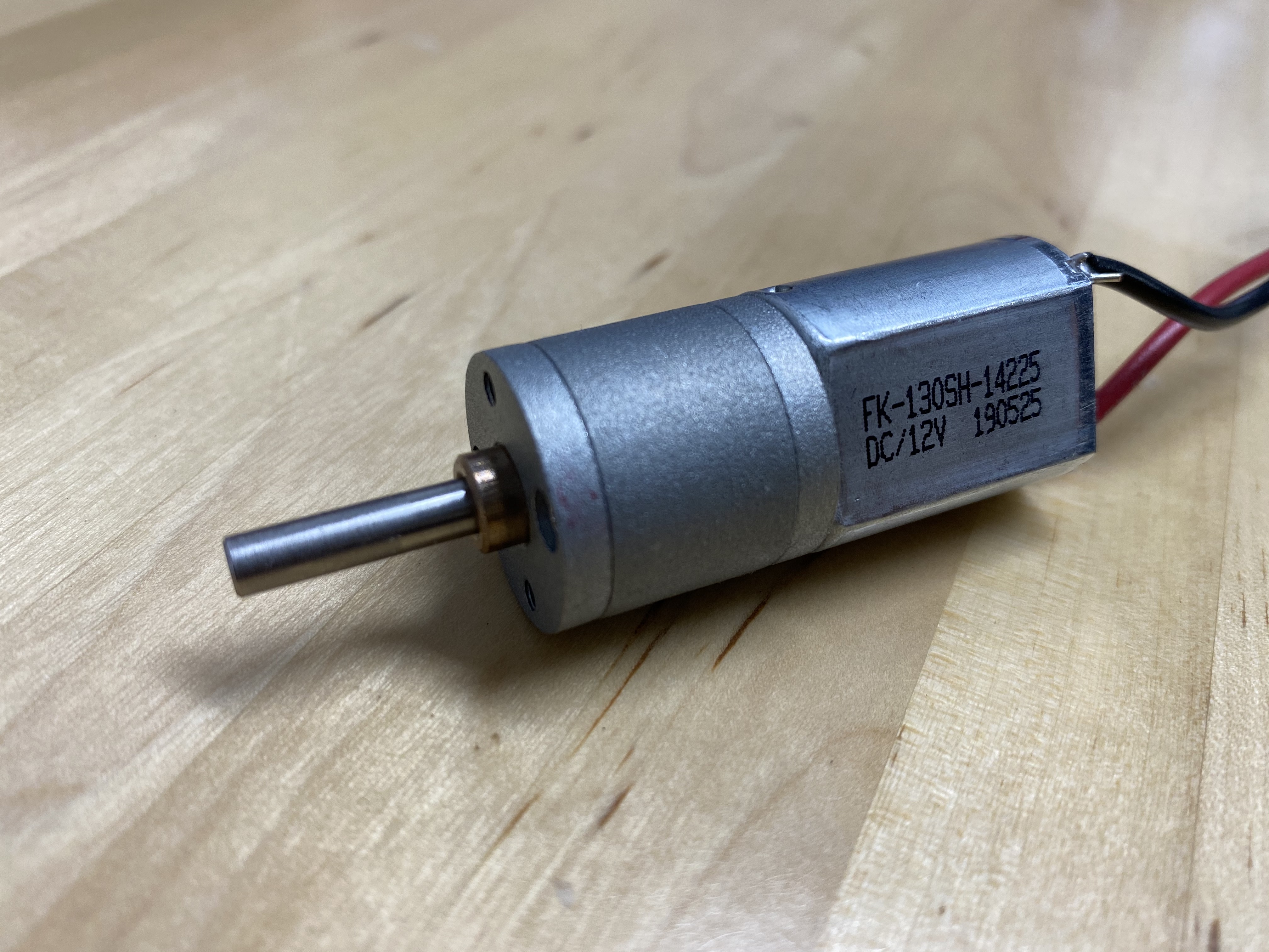
A gearmotor just means a motor that has a geartrain attached to its output shaft to give the motor more torque at the expense of speed. In the picture below, the actual motor is the metal case with “FK-130SH-14225” printed on it. The shape of the motor reveals its contents: the motor has two curved permanent magnets to create a magnetic field across the rotor. The flat sides of the case are where no magnets are needed.
The cylinder with no labels is the gearbox.
Using a DC gearmotor is pretty simple: you give it a constant voltage. If you want it to spin faster or generate more torque, you raise the voltage. If you raise the voltage too far, the insulation in the coils melts, and you need a new motor.
Usually, we run DC gearmotors at higher voltage than we need, and then reduce their speed using pulse-width modulation.
Stepper motors #
in most situations involving motors, you want them to spin continuously for a long time. Stepper motors are designed for the situation in which you want a motor to rotate to a certain position, and then stop very precisely. They’re common in printers (both 2D and 3D) and all sorts of robots. You could make a stepper motor spin continuously to run, say, a fan, but it would be less efficient and more expensive than other motors.
Here’s what a stepper motor looks like.
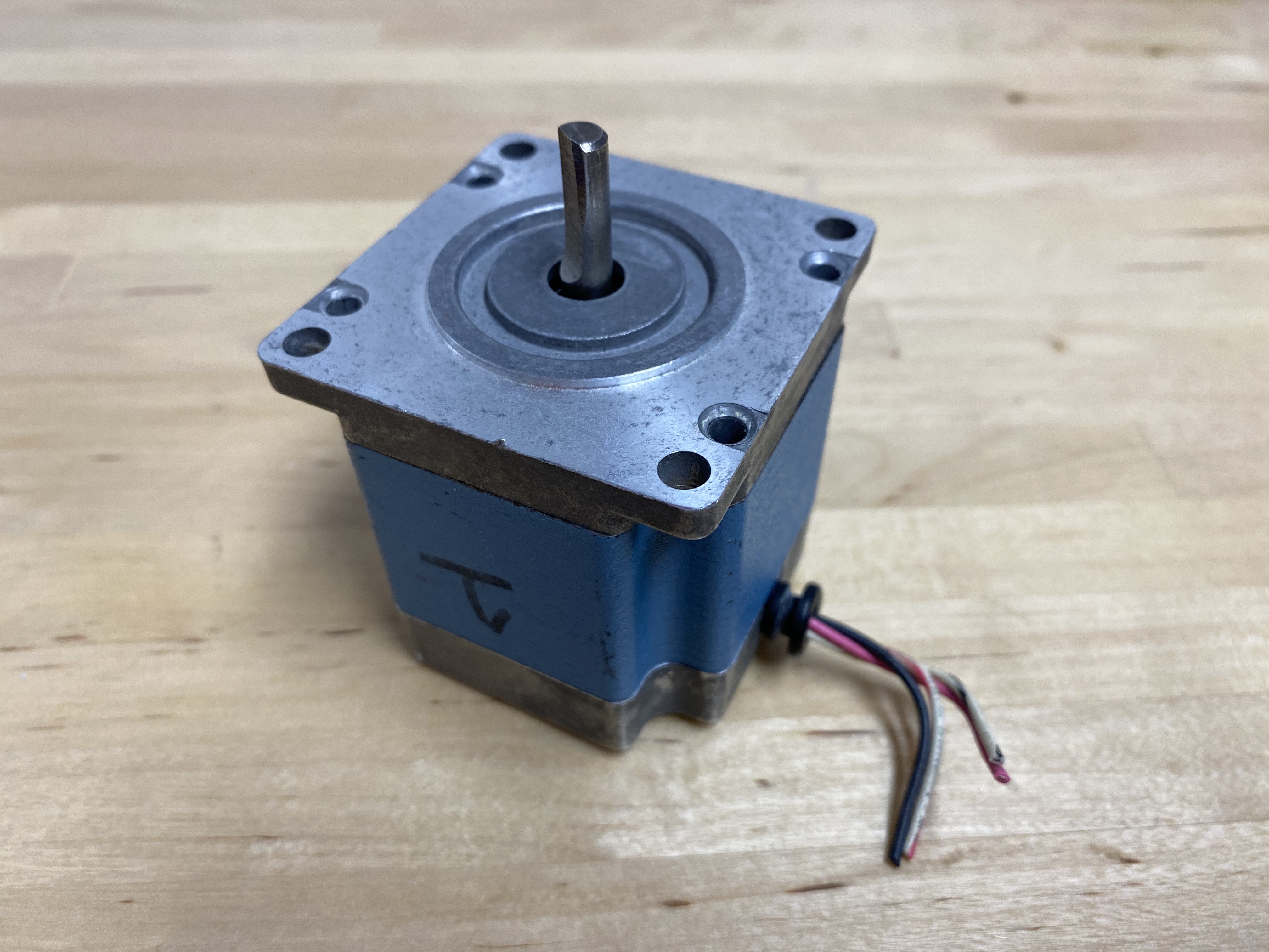
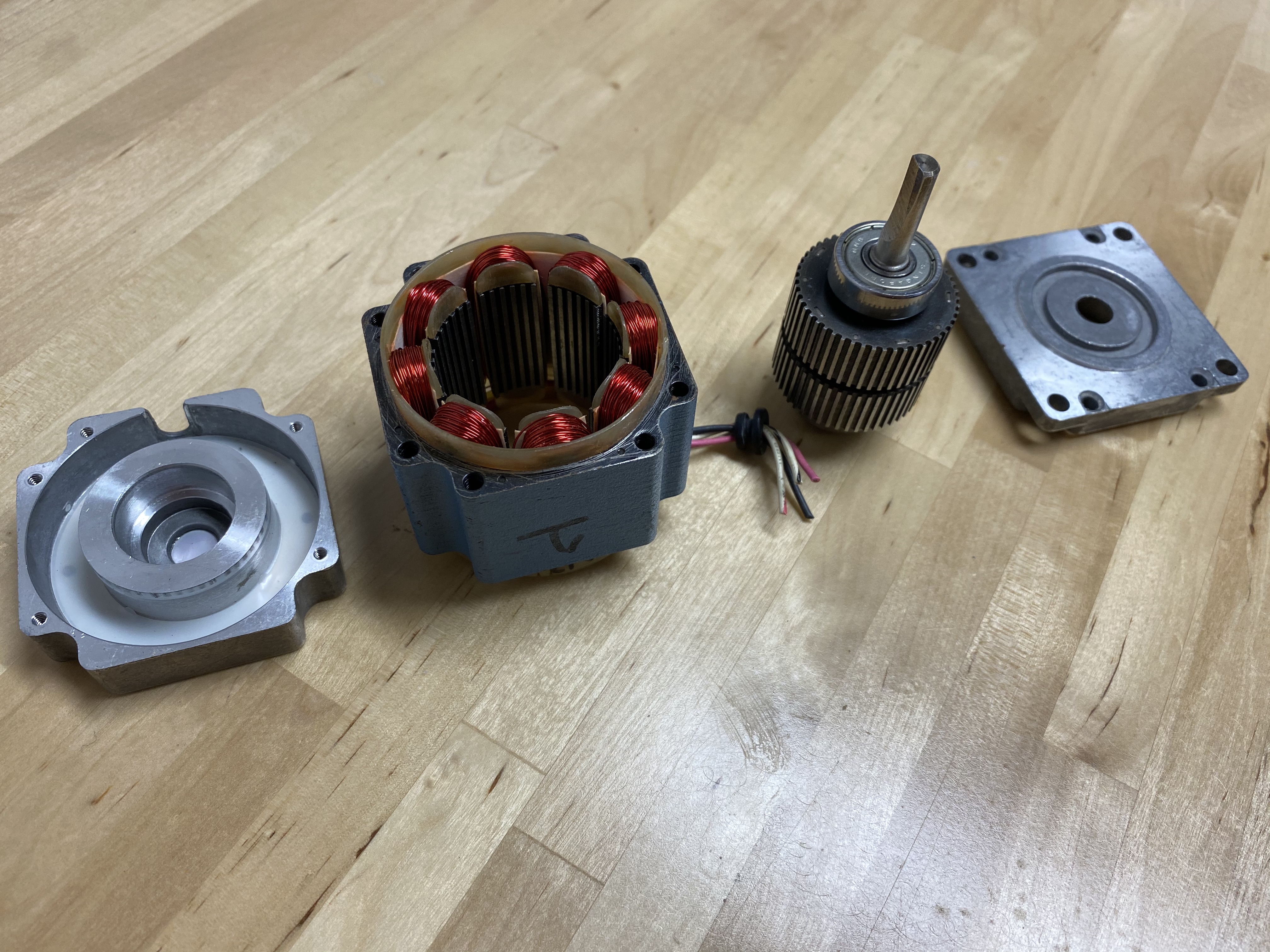
Inside, it has a rotor that consists of a large permanent magnet capped in iron cups that look like gears. The teeth of the cups are offset from each other by one tooth; they don’t line up.
The stator has two sets of coils. When a magnetic field is applied to the rotor with one set of coils, one of the cups lines up with the field more than the other. Then, when we switch current to the other set of coils, the other cup lines up, and the motor takes a step. By alternating back and forth, the motor steps in a circle.
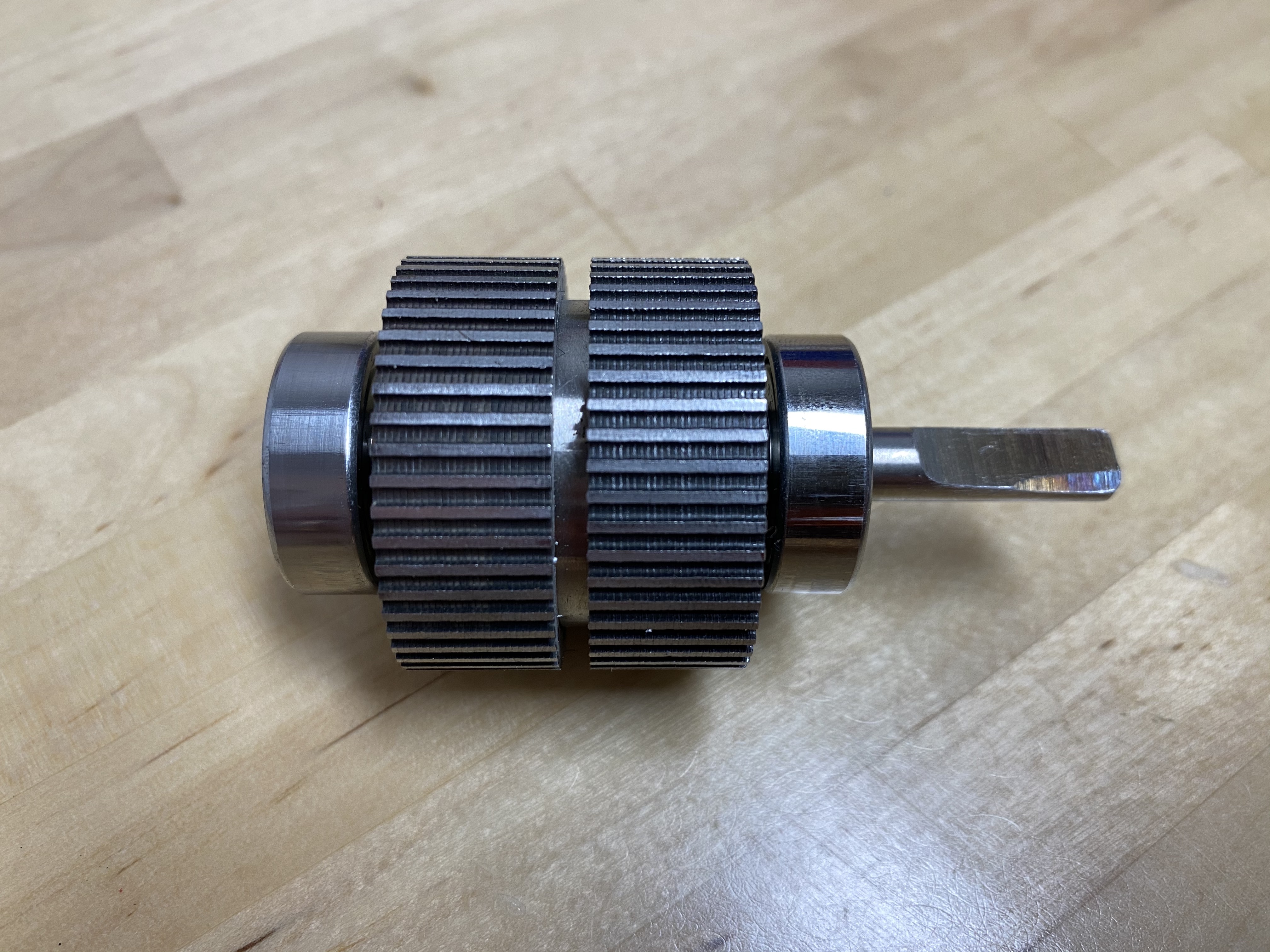
If you look closely at the rotor below, you can see that the teeth on the left rotor cup are not lined up with the teeth on the right rotor cup.
How do I control a stepper motor?
You need two H-bridges for stepper motor control – one for each of the coil sets. To learn about how to wire a stepper motor to a pair of H-bridge motor controllers, view this resource.
Circuit Python code for stepper motor control can be found on the KB2040 programming page, here.
Hobby servos #
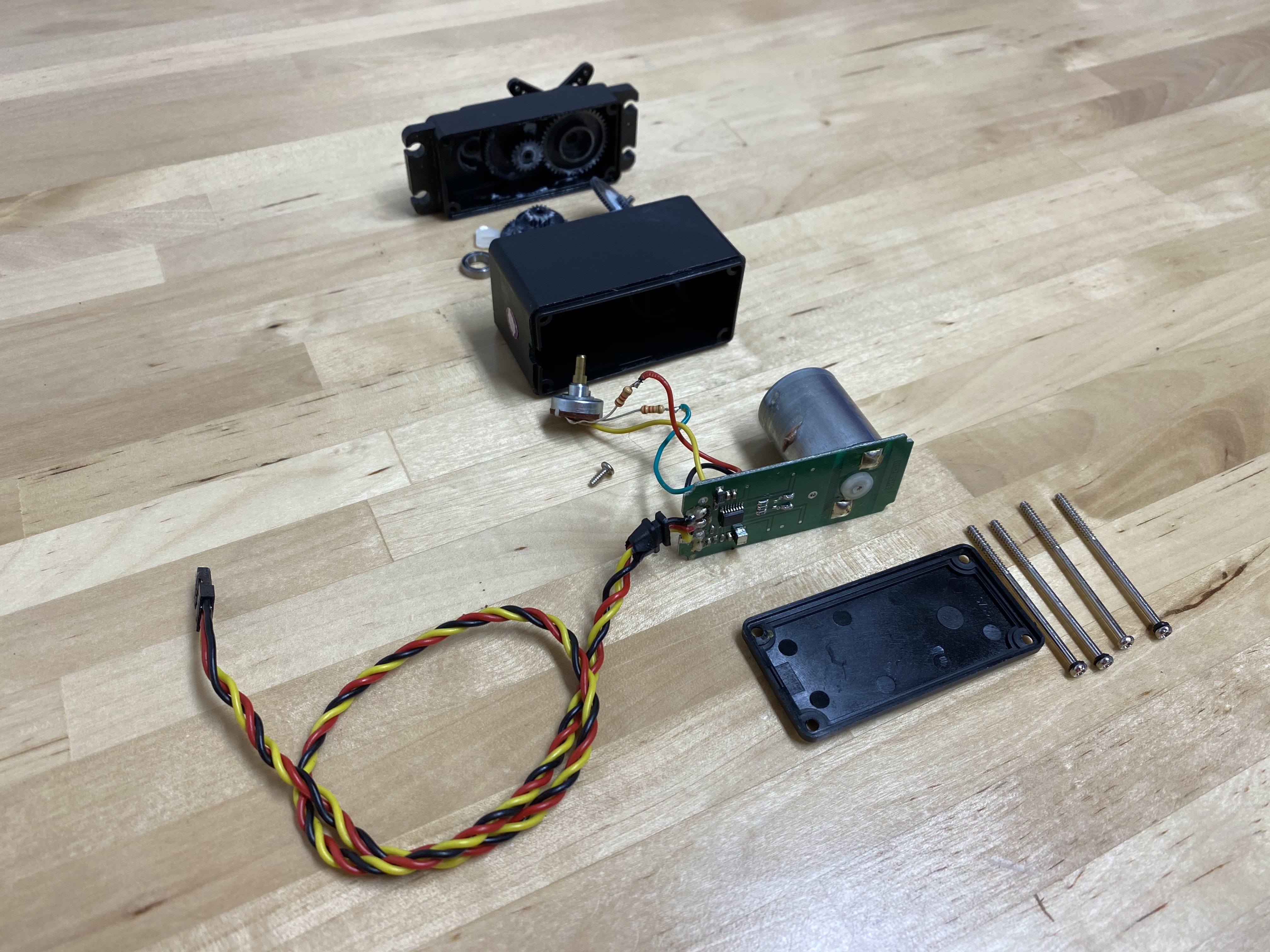
Okay, now we have to expose a lie: the hobby servo is, in fact, a brushed DC motor hidden inside a plastic case, so the truth is that we’re only discussing two kinds of motors. The case also contains a geartrain, a motor controller IC, an H-bridge and a potentiometer.
Here’s what a hobby servo looks like, inside and out.
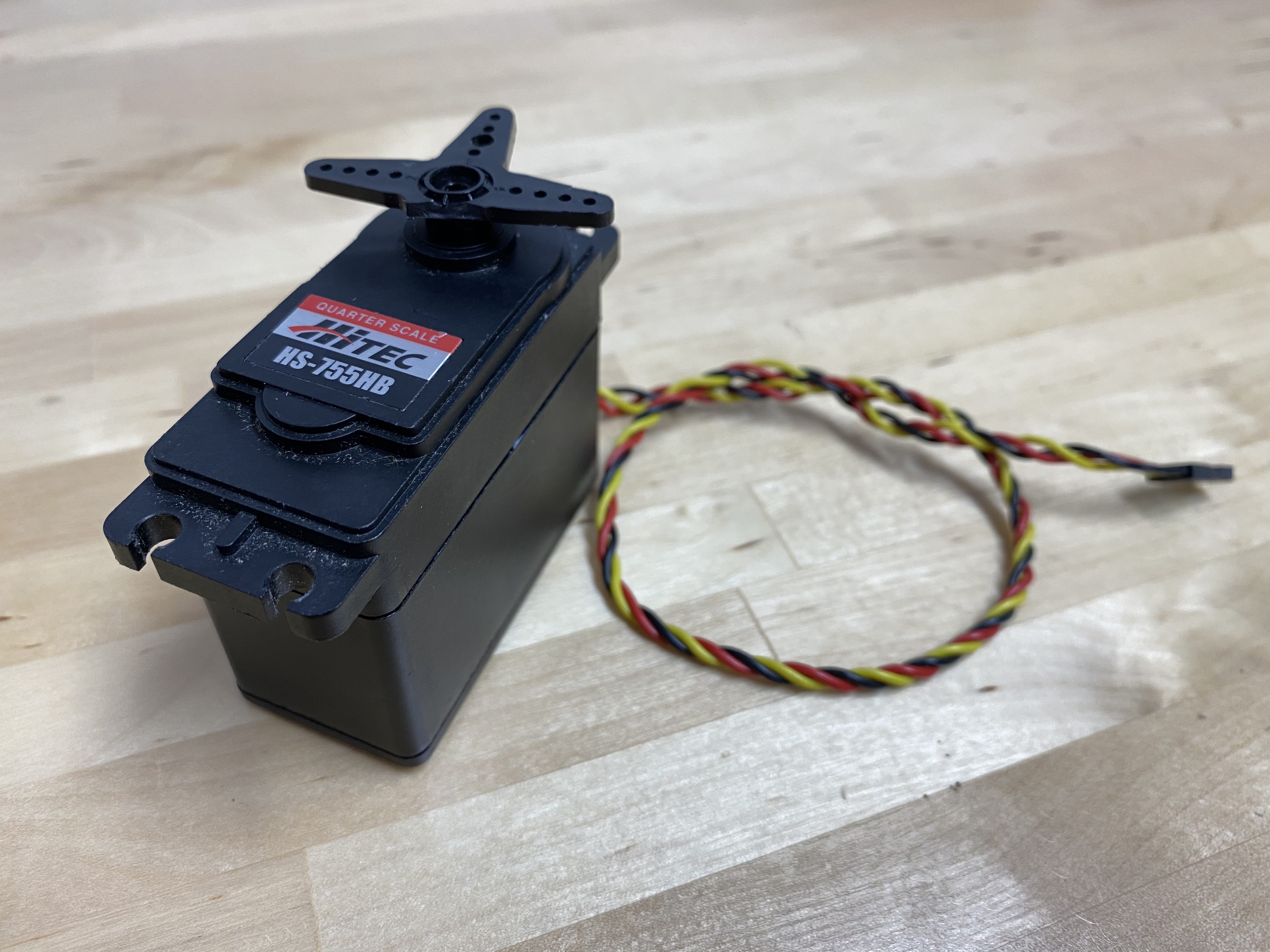
Hobby servos are great for position control, but they usually have a limited range, from 0-180 degrees. They are frequently used in the steering systems of RC cars, which is where the “hobby” name comes from. The plastic T on the top of the servo is called the “horn,” and it can be replaced with different shapes, like crosses and disks. You can get a small, weak, plastic-geared SG90 hobby servo for around $2. More powerful hobby servos with metal gears can run up to $100.
To control the servo, you send it a digital pulse 50 times per second. The length of each pulse represents a command to the servo to move to a certain position. The length of the pulse can range from 1-2 ms, with 1 ms corresponding to spinning all the way in one direction and 2 ms corresponding to spinning all the way in the other direction.
On the underside of the PCB is a Hitec HT7003 analog controller. This chip looks at the voltage on the potentiometer, compares it to the control signal, and then drives the motor via the H-bridge to make the potentiometer match the control signal.
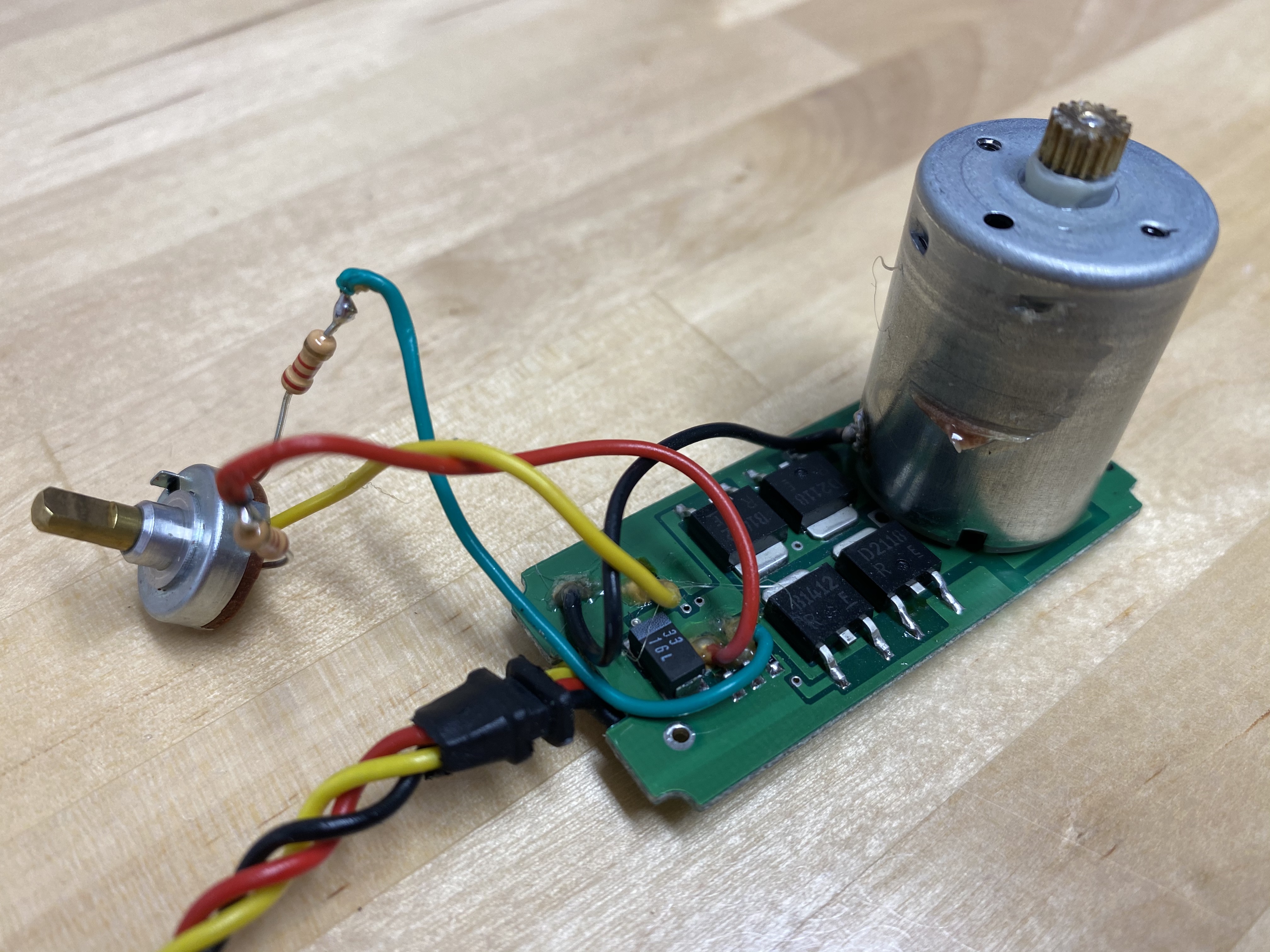
On the PCB next to the motor, you can see the 4 transistors that make up the H-bridge. The servo uses two Rohm 2SD2118 NPN power transistors and two complementary 2SB1412 PNP transistors. MOSFETs would also work here, but would probably be more expensive.
Sparkfun has a good hobby servo explanation if you want more details.
Motor selection #
How do you actually go about selecting and buying a motor?
Here are a few steps you could run through.
1. Decide what kind of motion you need. #
If you need to rotate continuously, a brushed DC or universal motor is a good choice. If you need to control position, like in a 3D printer or robotic arm, a stepper motor is better. If you just need to twitch back and forth across a small angle, a hobby servo might be a better choice.
2. Figure out how much power you need. #
This is why you took Dynamics last semester. However, as you’ll see in the following example, a full dynamics model is more useful in some scenarios than others.
3. Check your various budgets: how much can you spend, but also how big or heavy can the motor be? How many motors do you need? Just one for a prototype, or 100,000 for a production run of your new electric pogo stick? #
For low power, cheap motors, you’re in a bit of a bind. Usually, cheap motors are poorly documented. You’ll get for a DC gearmotor, for example, a voltage rating and a no-load speed, like 12 V, 540 RPM. This suggests that if you apply 12 V to the motor with nothing attached, it will spin at 540 RPM. That tells you nothing about how fast it will spin when you load it down, unfortunately (though you can be sure it will be slower).
A decent selection method is to estimate your power, and then estimate the size of a motor that can handle that power. #
As a rough guide:
- A 1000 W motor is around the volume of a paint can (3.78 L).
- A 100 W motor is around the volume of a soda can (355 mL).
- A 10 W motor is around the volume of 5 Oreo cookies stacked up.
The gearmotor in your kit is rated for 2 W, and probably has a volume of around 1 Oreo cookie (not including the gearbox). This power rating is similar to most motors like this, called “type 130,” or “toy motors,” or “one of those ones like Mabuchi makes.”
Buy a motor that size, and try running it with your load at different voltages to see how it behaves.
Motor selection examples #
Motor power estimation example #1: Rotating photo cube. Imagine you’re making a gift for your mom - let’s say it’s a rotating photo cube that displays a different photo on each of its 6 faces. Each edge of the cube is 20 cm in length. You imagine it to be a desktop or countertop item, something like this, but with a motor in its base to rotate the cube continuously (which means a DC gearmotor is the best choice). You plan to have the motor shaft directly coupled to the pin that extends down from the bottom corner of the photo cube.
What torque and speed does the photo cube’s motor need?
Speed: A desirable rotation rate would be about 10 rpm, which would give the viewer 6 seconds to see all the photos on the cube as it completes one revolution.
Acceleration: It doesn’t really matter if the photo cube takes a bit of time to accelerate up to its operating speed, but it seems like it would be more ideal if there’s not to much of a lag. Let’s say you’d like it to get up to speed within a quarter of a second.
Then, angular acceleration = (angular velocity) / (start-up time).
Using 10 rpm as your angular velocity and 0.25 sec as your delta t, and converting rpm to rad/sec, you get 4.2 rad/sec^2 for angular acceleration.
Torque: The motor needs to provide torque to:
(1) overcome the friction between the cube and its frame and
(2) accelerate the rotational inertia of the cube.
Assume the frictional torques are orders of magnitude lower than the inertial torque. In other words, if the motor supplies enough torque to initially accelerate the cube, there will be enough torque to overcome friction during rotation.
Torque = (mass moment of inertia) x (angular acceleration)
Let’s estimate the mass of the cube at 0.5 kg, and its side length to be 20 cm. We can then use the formula for the mass moment of inertia of a cube, I = (1/6)x(mass)x(side length)^2, to find I = 0.0033 kg-m^2.
Torque = (0.0033 kg-m^2) x (4.2 rad/sec^2) = 0.014 Newton-meters = 14 milliNewton-meters
That’s in SI units; you can also convert it to the imperial units of 2.0 ounce-inches.
An alternate way to estimate torque is to anticipate the force you’d need to apply at the edge of the cube to set it in motion. (This approach also assumes negligible friction around the axle.) Assume a finger tap will do it, and that’s about 0.1 N of force. If 0.1 N is applied at a 10-cm moment arm from the motor shaft, the torque is 0.01 Newton-meters, or 10 milliNewton-meters. This result is satisfying because it’s the same order of magnitude as the first approach.
So, you want a motor that can provide a torque of 14 mN-m and a speed of 10 rpm, or 1.0 rad/s.
Power: Since power = (torque) x (rotational speed) = (14 mN-m) x (1.0 rad/s), you’re looking for a motor with power of 14 milliwatts. Not much!
Did this dynamics analysis help you? Not really! Even without those calculations, you probably knew this was a very low power application. Any cheap low-torque gear motor would probably be fine, with its speed slowed down either with a gearbox (which would also increase its torque) or via pulse-width modulation. You would have been better off focusing on the size of your picture frame base and choose a cheap DC gearmotor that fits into that size and shape profile.
Motor power estimation example #2: Helicopter rescue hoist. Let’s consider a completely different motor application, in a context where you’d want to be sure to get its specifications correct.
Imagine you’re designing a helicopter rescue hoist, which lifts survivors from emergency situations by reeling in a basket attached to a cable. A motor-driven winch winds a cable around a spool on board the helicopter. How much motor power is needed here?
Torque: You’d probably want to make sure the rescue hoist can lift at least 1000 lbs. If the cable tension is 1000 lbs, and the cable spool has a 1-foot radius, the motor torque would need to be 1000 lbs-ft, or 1355 N-m.
Speed: Hoists in industrial warehouses typically lift loads at 10 to 25 ft/min, but in an emergency situation, like a wildfire, a faster lift could be necessary. Let’s aim for the capability to lift the survivors at 60 ft/min. That’s clearing the height of a 6-story building in one minute.
What rotational velocity is needed for the spool to lift the cable at a rate of 60 ft/min?
The cable will be wound around the spool at a rate roughly equal to the (spool circumference) x (rotational velocity).
Rotational velocity = (lifting rate) / (spool circumference) = 60 ft/min / (2 * π * 1 ft/rev) = 9.55 rpm, or 1 rad/sec
Power: Power = (torque) x (rotational speed) = 1355 N-m x 1 rad/sec = 1355 watts
This is definitely a back-of-the-envelope calculation, but we’ve at least learned that something like a 2 kW motor is in order.