In-class exercises for Fall 2025 #
1: Power an LED with “wall” power (Class 1) #
For a warm-up activity, let’s power an LED with “wall” power and control it with a push button.
Your goal is to create a circuit on your breadboard that lights up an LED with power from the wall, directed through your kit’s DC power supply. This circuit should have the following characteristics:
- It is implemented on a breadboard.
- It accepts power from a 2.1 x 5.5 mm plug from a 12 V wall adapter.
- It turns on an LED when a push button is pressed.
The components are:
- DC power supply
- One power (barrel) jack
- One LED
- One resistor (What size? See these notes.)
- One pushbutton
- Various wires and a breadboard
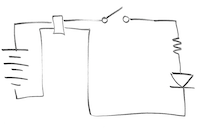
The image below is a circuit diagram representation of what you’re building.
For an extension to this exercise, re-arrange your circuit so you have one LED that stays on permanently and another that is powered by the button.
Important note: the pins on the power jack are weird! More details below.
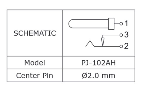
There’s a cryptic diagram in the datasheet for the PJ-102AH power jack, shown below.
One part is obvious: the pin in the middle is connected to pin 1.
But what is that little arrow/bump thing with pins 2 and 3?
That’s trying to tell you that when the jack is empty (i.e. no plug inserted), pins 2 and 3 are connected together. When you insert the plug, the barrel pushes on the bump at the end of the pin 2 contact, which bends it away from the pin 3 arrow, breaking the connection to pin 3. It’s so that you can detect whether there’s a plug inserted or not, which can be useful for battery-powered systems. You don’t need to implement that feature on your regulator board; you can just use pins 1 and 2.
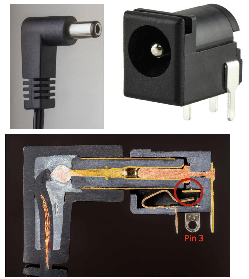
In the cross-section view of a barrel plug inserted into the jack, you can see how the outer sheath of the plug makes contact with pin 2 and also how the plug breaks the continuity between pin 3 and pin 2.
Image credit: E. Schlaepfer and W. Oskay, 2023, Open Circuits, opencircuitsbook.com
2. LED circuit details (Class 2) #
Would the functioning of Circuit A (left) be any different than that of Circuit B (right)? Why or why not? What evidence would prove your answer?
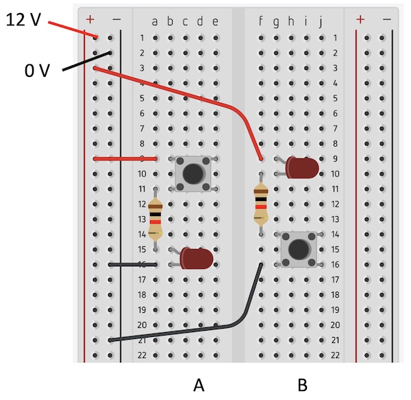
Does it matter if the resistor is “above” or “below” the LED?
3. Safety check (Class 2) #
-
If you feel a circuit component getting hot or starting to smoke, what should you do first?
a) Call over an LA
b) Take the component out of the breadboard
c) Unplug the power supply (e.g., barrel jack) from the breadboard
d) Use your multimeter to measure the voltage across the component
-
What is a possible result if your multimeter dial is turned to the “mA” symbol and you put your multimeter probes between a high and low voltage location on a circuit?
a) You’ll get zero current reading on your multimeter and prevent your circuit from working
b) You’ll let too much current go through your multimeter and blow its fuse
c) You’ll hear a beeping sound warning you that you should use the “A” symbol and port
-
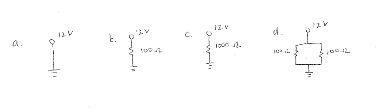
Which of these three circuits can you safely build on your breadboard? (hint: the resistor power rating is 0.5W)
4. Current limiting resistors (Class 2) #
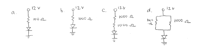
Which circuit gives the brightest LED?
5. Build voltage dividers (Class 2) #
We’ve used resistors to limit current flow through an LED.
Let’s see how we can also use them to reduce a voltage so we can supply a specific lower voltage to a device. For example, we might be using a 12 V power supply but want to supply only 5 V to an Arduino or other microcontroller.
Read more here about using resistors as current limiters and voltage dividers.
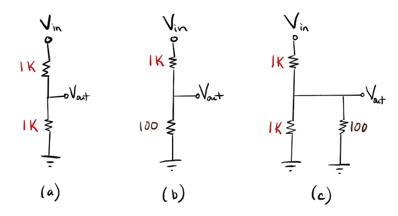
For each of the set-ups below, provide 12 V as V_in, and predict the output voltage V_out.
After you’ve written down your predictions for V_out, build the circuits and use your multimeter to measure V_out. If your predictions were off, try to figure out why.
6: Matching schematics to breadboards (Class 3) #
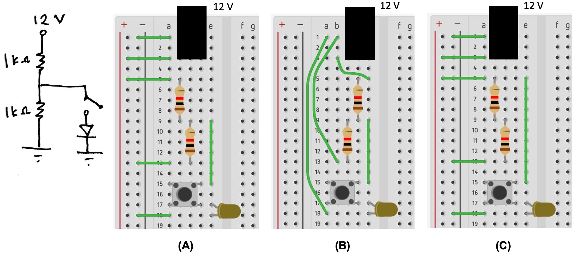
Which of these breadboards has the same circuit as the one represented in the schematic?
7: Build a voltage regulation circuit (Class 3) #
This is an introductory exercise designed to help you get familiar with breadboard prototyping while also building a basic circuit that will be useful for later exercises and projects. It forms the basis for Project #1, but you don’t need to think about that yet. If this is all new to you, look at the pages on breadboard prototyping and multimeters.
Your goal is to put 4 components and some wires on your breadboard to achieve this goal: 12 volts go in; 5 volts come out.
The 4 components are:
- One power jack
- One L7805CV voltage regulator
- Two capacitors
8: Review of voltage and current (Class 3 and 4) #
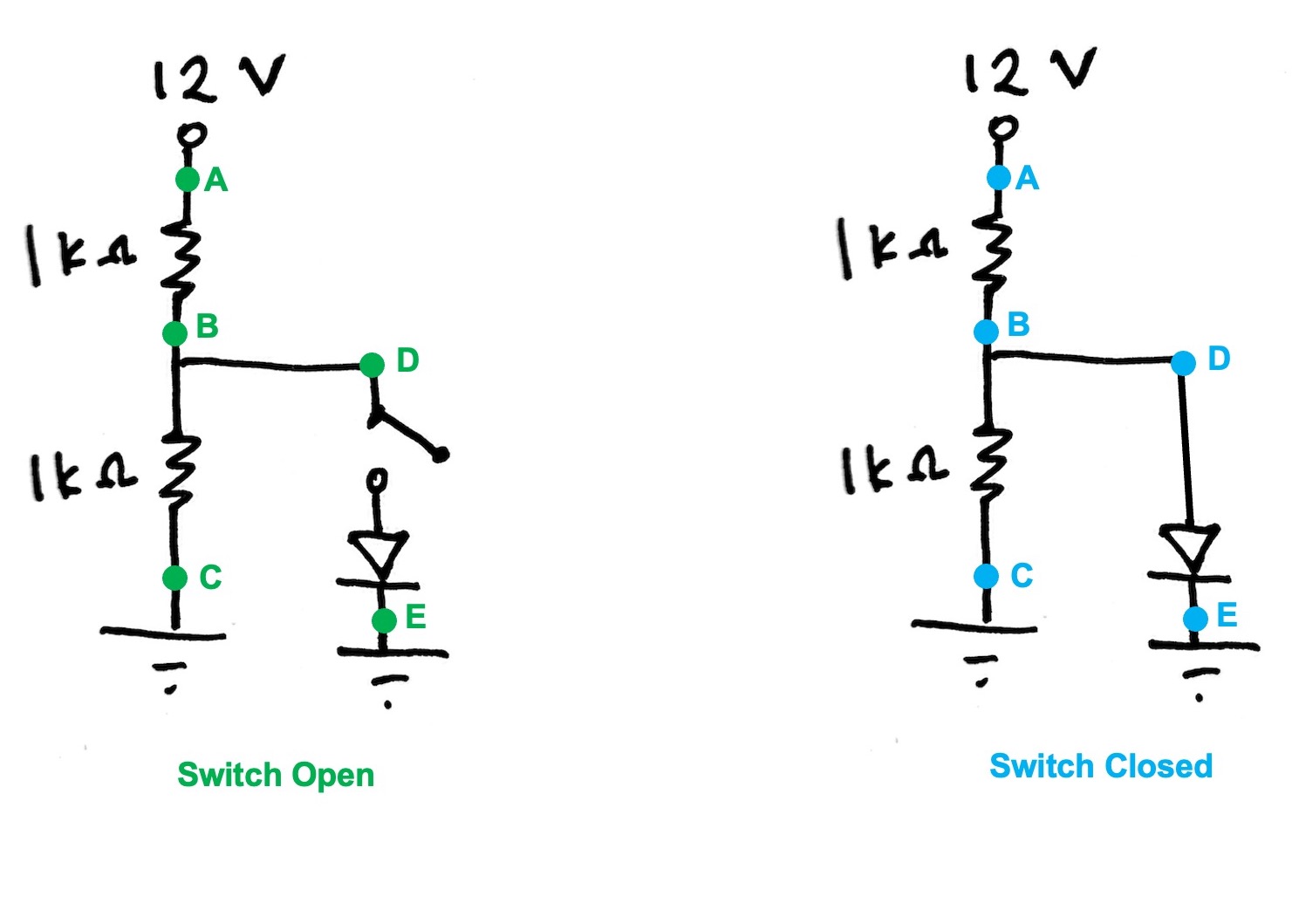
For the circuit below, analyze the following first for when the switch is open, and then for when the switch is closed:
- Find sets of labeled points on the circuit where the current is the same.
- Identify any points on the circuit where no current is flowing.
- List the points in order from highest current flow to least current flow.
- Find sets of points where the voltage is the same.
- At what points should the voltage be near 0 V (e.g., ground)?
- Order the points from highest to lowest voltage.
9: Discharge a capacitor and observe the RC time constant (Class 4) #
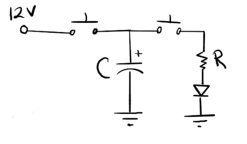
- What sequence of button presses makes the LED flash, and then fade out?
- In your kit, you have resistors of size 100, 1K, 10K, and 100K ohms. You also have a 10 microfarad capacitor, and we’ll give you a 100 microfarad capacitor for this exercise. What combination of R and C values will produce the slowest rate of fade for the LED (that you can observe)?
- Try to explain why the rate of fade varies with R*C. (We can look at this mathematically as well.)
10. Control a motor with a BJT (Class 7) #
Making a motor spin is pretty simple: apply sufficient voltage across its leads. When we want to control things like motors (or LEDs, buzzers, etc.) electronically, instead of plugging them in to breadboards with our hands, we use transistors. The goal of this exercise is to use a bipolar junction transistor, the 2N3904, to turn on and off a motor.
You need 5 things in addition to the usual 12 V power supply and barrel jack:
- A 3.3 V voltage source, like the voltage regulation circuit you built previously
- A 2N3904 transistor (or really any transistor is fine, if you know the pinout)
- A DC gear motor
- An appropriately-sized current-limiting resistor for the BJT
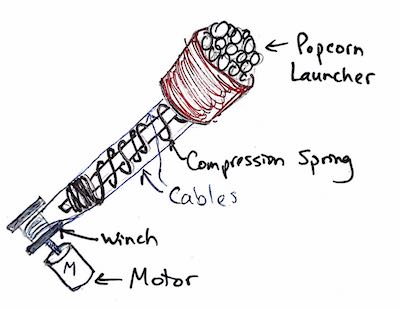
The picture below shows the concept of what you’re building.
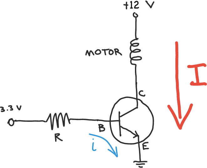
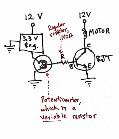
Extension: Add a potentiometer (a variable resistor) in series with the base and use it to vary the current flowing from base to emitter. Notice how this works as a crude motor speed controller, but also notice (carefully!) how the BJT heats up as more current is drawn through it.
11. Determine pin voltages and ideal resistor value for a BJT circuit (Class 7 and 8) #
- For the circuit shown in Exercise #10, fill in the table below to indicate the voltage at E, B, and C when the base resistor is connected to (a) 0 V and (b) 3.3 V.
- To run your kit’s gear motor, what is an ideal value for the resistor between 3.3 V and the base of the transistor?
Useful info:
- Your motor draws 150 mA of current when spinning unloaded, and on the BJT data sheet you can find the “current gain” of the BJT (between its B-E path and C-E path).
- You can find the “saturation” voltage of the BJT B-E junction on its data sheet.
- “Saturation” is the state when a transistor has enough energy at its base for the electrons to flow through the C-E (collector-emitter) pathway. In other words, saturation = ON.
| V_E | V_B | V_C | |
|---|---|---|---|
| Input at O V | |||
| Input at 3.3 V |
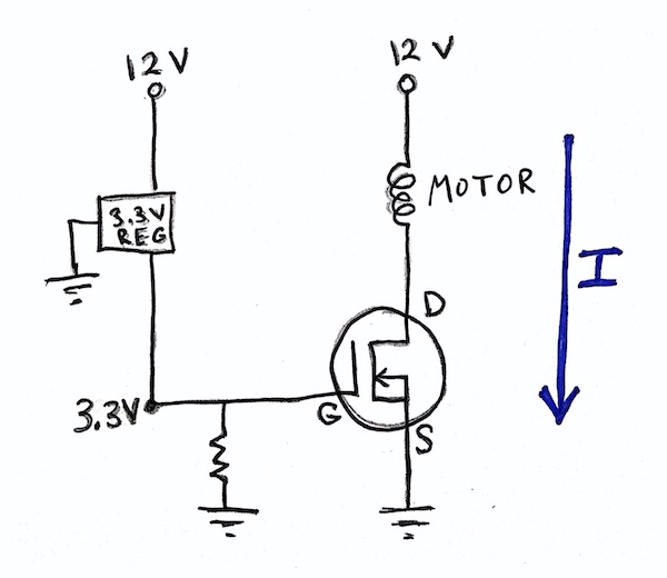
12. Control a motor with a MOSFET (Class 8) #
You’ve used a bipolar junction transistor to control a motor. Now try using the other main class of transistor: a metal oxide semiconductor field effect transistor, or MOSFET. The main difference between the two types of transistors is that BJTs are current-controlled, and MOSFETs are voltage-controlled.
You need 5 things:
- 3.3 V voltage source, which you can make using the 3.3V regulator in your kit
- 12 V voltage source
- An N-channel MOSFET
- A DC gear motor
- A pull-down resistor for the MOSFET
13a. P0 takeaways (Class 10) #
Add a thought to this shared doc:
https://docs.google.com/document/d/1WWe9YpnqQwaxn9oNP9B09x3XFFOUSrDopJ1wqWNpExg/edit?usp=sharing
13b. De-bugging challenges (Class 10) #
Study the three circuits pictured here. Identify the errors preventing them from working: https://tufts.box.com/s/ggy1y8svs4tuulywfwx7mzdyxvlrjcyo
14. KB2040 microcontroller challenges set 1 (Class 10 and labs) #
Learn to program your KB2040 board by working through the first 6 of these 12 challenges: http://andnowforelectronics.com/notes/kb2040-challenges/
You’ll want to consult the KB2040 programming resources.
For a 1-page summary of the most important Circuit Python commands for your KB2040, click:
https://tufts.box.com/s/lczswqulqewphbxyku1zpvazp73govzi
15. Project 2 takeaways reflection (Class 11) #
(a) What are some problems you encountered along the way of working on your game for Project 2, and what did you learn from them? Let’s collectively document those.
(b) If you’re ready to do so, take a moment to fill out the self-assessment for Project 2.
16. Recognizing common errors in KB2040 Challenge #6 (Class 11) #
Challenge #6 asks you to control a motor’s on/off state with a KB2040 output pin. Below are two approaches to setting up the circuitry. Each has problems that will prevent it from working correctly. What do you think those problems are?
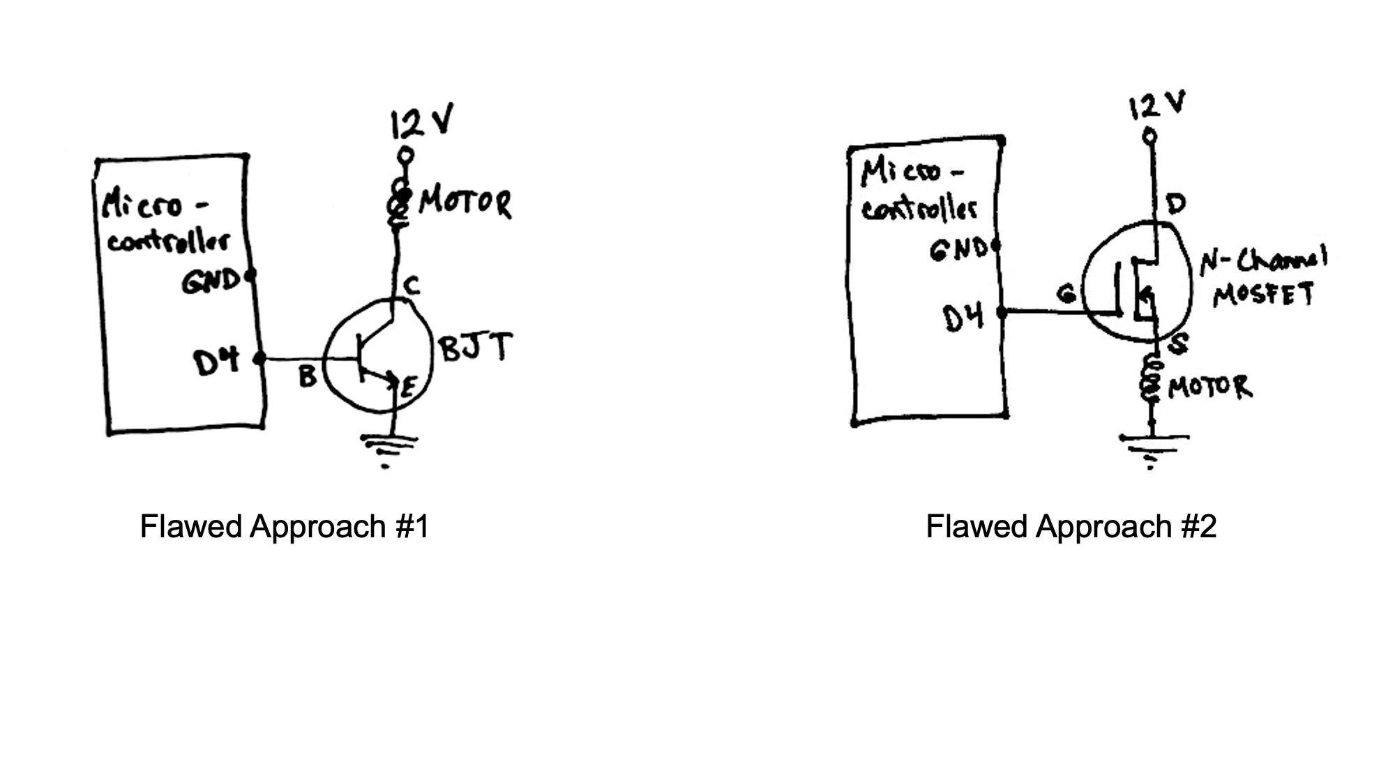
What are the problems with approach #1?
What are the problems with approach #2?
17. Mechanically controlled two-way motor circuit (Class 11) #
With a partner or two, build a circuit that will allow you to use pushbutton switches to toggle a 12-V DC motor between the states of (a) OFF (b) ON counterclockwise, and (c) ON clockwise. That means your motor needs to be able to draw current in either direction (only one direction at a time). Your circuit should NOT use transistors. It should include (a) 12 V adapter and barrel jack, (b) DC gearmotor, (c) assorted wires, (d) as many pushbutton switches as you want.
As you work on this challenge, be careful not to create a situation where you are sending 12 V to ground only through wires. That’s a short circuit and will cause heat and smoke!
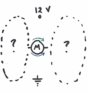
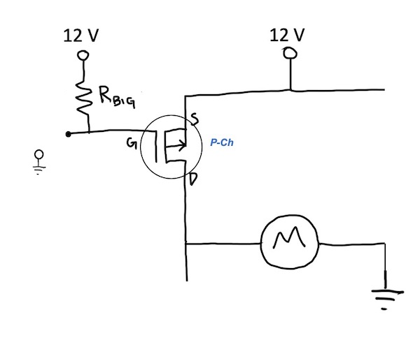
18. H-bridge circuit analysis (Class 12) #
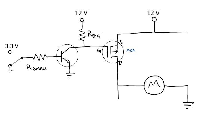
(Worksheet version of this will be handed out in class.) You’ve just wired up the top left corner of an H-bridge circuit using a P-channel MOSFET. You connect the other motor lead to ground so that you can test this corner before wiring up the transistors at any other corners. If this corner is wired correctly,
- What should happen to the motor when the MOSFET gate is connected:
- to 12 V?
- to ground?
- For each of those gate states, determine the voltage at the MOSFET’s three pins, and sketch the path of any current that flows anywhere in the circuit.
Now you add a BJT as a different method for switching on the P-channel MOSFET. Again, you want to test this corner before moving on to other sections of the H-bridge. If the BJT and P-channel MOSFET in this corner are wired correctly,
- What should happen to the motor when the control voltage heading toward the BJT base is:
- at ground?
- at 3.3 V?
- For each of those control voltage states, determine the voltage at the MOSFET’s three pins, and sketch the path of any current that flows anywhere in the circuit.
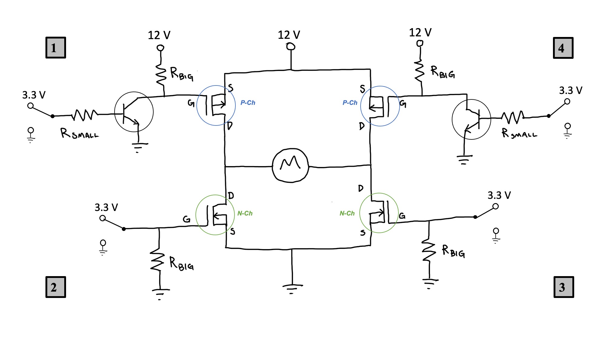
19. H-bridge circuit analysis, part 2 (Class 13) #
This H-bridge circuit has four inputs, shown at locations 1, 2, 3, and 4. Each input turns a transistor on or off.
If all four switches were connected to 3.3 V (as shown below), what would happen and why?
20. Test the current limit of your P1 PCB (Class 14) #
The voltage regulators on your P1 PCB are specified (on their data sheets) to be able to handle current at the level of 1.5 A (the 5V regulator) and 0.8 A (the 3.3 V regulator). But the question is - once soldered into your P1 PCB, can they still perform up to their specified max current limit?
Test your P1 PCB by determining how much current your regulators can actually send out to loads at your output pins before going into thermal shutdown.
General procedure (details left to your group):
- Determine the resistance (it will be a low value!) you should attach to your 3.3 V and 5 V output so that something close to the specified max current is drawn (0.8 A or 1.5 A, respectively). Also compute the power that will be drawn through the circuit at these voltage and current conditions.
- Find a way to create that resistance using a combination of provided resistors (in series and/or parallel). You must also be sure that your resistor set-up provides enough have enough power dissipation capacity. For example, if you need to be able to handle 1 W, and your resistors are 0.5-Watt resistors, you need at least two resistors.
- Attach your resistor set-up to the output. These resistors stand in for a motor or other load to which you would want to supply 3.3 V or 5 V
- Monitor the voltage drop across that resistive load - that is, the voltage drop between the output of the regulator and ground
- If that voltage drop begins to decrease lower than 3.3 V or 5 V, your regulator has gone into thermal shutdown (you may feel the regulators getting very hot before this happens).
Use this shared doc to post questions about the P1 PCB test and about P3 circuit board design.
21. Measure a DC gearmotor efficiency (Power Out and Power In) (Class 14) #
Here are a few basic measurements you can make to understand your DC gearmotor better. The overall goal is to determine the efficiency of the motor by comparing the electrical power that goes into it (“power in”) with the mechanical power it delivers (“power out”).
Power Out (Mechanical Power)
Determine how much mechanical power the motor actually delivers (“power out”). One way to do this is to measure the time it takes to perform a certain amount of work (i.e., to add energy to a system).
- Use tape and string to hang a water bottle (or other weight) from your motor shaft.
- Connect your motor directly to your 12 V DC power supply using alligator clips.
- Measure the time it takes your motor to lift the water bottle (or other weight) a specific distance (you could try something like 0.5 or 1.0 kg of water, lifted up 1 m).
- Measure the weight your motor was lifting. Compute the amount of work done in lifting the water.
- With the two values of work and time, you can find “power out” - the mechanical power exerted by the motor.
Power In (Electrical Power)
Put your multimeter in series with the motor, and measure the current the motor draws when lifting the weight (using the same weight from above). You should switch your multimeter to the A setting (for Amps), and move the red lead to the port on the left side of the meter that is labeled “A”. The black lead stays in the black port labeled “COM”.
Efficiency
Compare “power in” and “power out” to estimate the motor’s efficiency.
Max Motor Power (Electrical)
While we’re at this, let’s also determine the maximum current that the motor draws.
Your motor draws max current when it’s working as hard as it can but not able to move its shaft due to the resistance it’s encountering. That’s called motor stall.
Use your multimeter to measure the resistance of your motor when not powered - i.e., when not moving. Divide 12 volts by that resistance to find the max current your motor is capable of drawing.
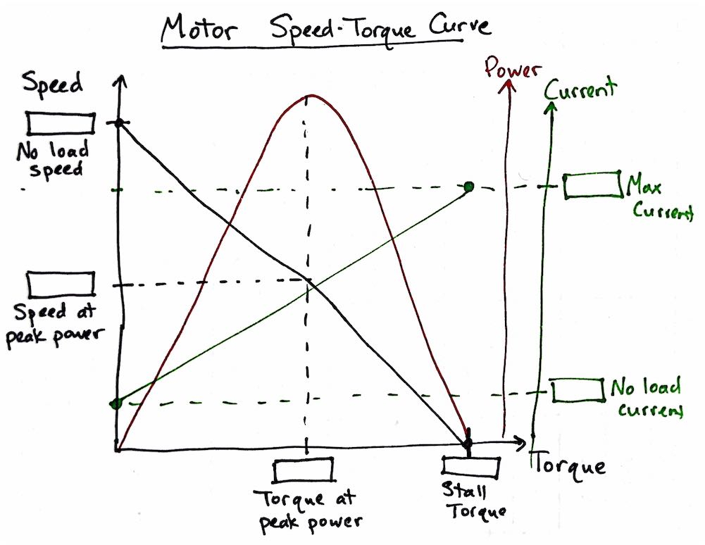
22. Motor speed-torque curve (Class 14 or 15) #
Fill in values in the boxes to complete the motor speed-torque curve for the DC gearmotor in your ME 30 kit.
23. Motor selection cases (Class 15) #
For each of these potential motorized game designs, determine whether the mechanical power and torque needs are within the capabilities of the DC gearmotor in your ME 30 kit.
- Can your motor handle these designs with a direct-drive approach (i.e., no gear trains or pulleys)? Why or why not?
- If your motor can’t handle the design via direct-drive, can it do the job with a gear train or pulley transmission? Why or why not?
Work in a small group and post your answers to this google doc: https://docs.google.com/spreadsheets/d/18il0YS9v-0mt79J7DdHGnpuPw71HNZ7vh3b1nPuhzdM/edit?usp=sharing
24. Analog and digital sensors (Class 16) #
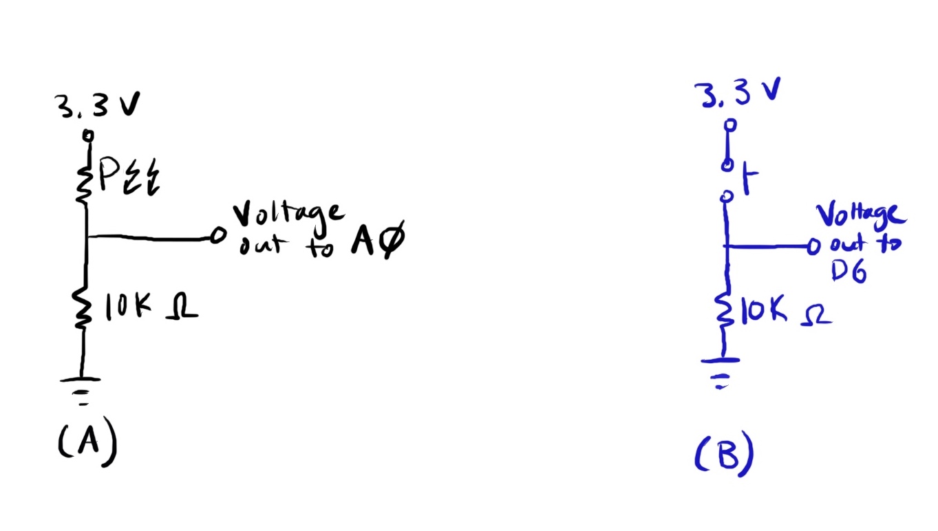
Circuits A and B show different ways to send a varying input to a KB2040 pin. Circuit A uses a photoresistor, a component whose resistance depends on the amount of light shining on it. Circuit B uses a simple pushbutton.
- Which of the set-ups below involves analog input to the microcontroller, and which involves digital input? Why? What will need to be different about your KB2040 code to measure voltage at A0 (in the photoresistor circuit) versus measuring voltage at D6 (in the push-button circuit)?
Build each of the circuits below and program your KB2040 to measure the input voltage from the point specified in the circuit. Answer the questions below.
- For Circuit A, vary the light level, and explore the range of voltages that your KB2040 pin receives (at the point specified in the schematic).
- How does the voltage at A0 relate to the light level (i.e., as the light level increases, does voltage at A0 increase or decrease)?
- How does the photoresistor’s resistance relate to the light level (i.e., as the light level increases, does its resistance increase or decrease)?
25. More practice with sensors and PWM (Class 16) #
Set up KB2040 challenge #10:
Use a resistor in series with your photoresistor to make a voltage that changes with light exposure. Use that voltage to control the speed of your gearmotor on pin D6.
Now try to add an LED whose brightness also varies with the light exposure to the photoresistor. Think carefully both about the code and the circuit components that you need to make this addition.
26. How to code your microcontroller to constantly check an input while also running actuators (Class 17) #
Suppose you want to check for the state of inputs while also running motors, lights, and other actuators.
In particular, try to do these three tasks at once:
- flash an LED (“led_1” in the code), 3 seconds on, 3 seconds off.
- constantly check for a button press that sets an input pin HIGH.
- flash a different LED (“led_2” in the code) when the button is pressed.
The naive approach #
Here’s a reasonable first attempt by a novice programmer to set up a microcontroller to check for input and flash a second LED when a button is pressed.
Why will this code probably not work very well to accomplish the goal stated above?
Try a state machine instead! #
Writing code for “state machines” is a better technique for this situation. At this link (and in the box below) is one way to set up state machines in CircuitPython.
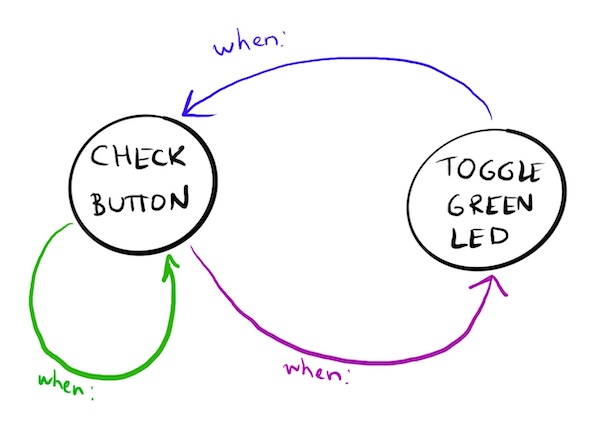
State machine algorithms can be conceptually represented by circles and arrows. Each state is represented by one circle. Arrows indicate what happens immediately after the commands in one state have been completed.
In the diagram below, add labels to the arrows to represent the rules for moving between the “CHECK BUTTON” and “TOGGLE” states.
27. Using a state machine with a motor (Class 17) #
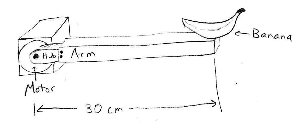
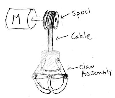
Imagine a Project 4 game with a 1-foot arm attached to the DC gearmotor shaft. Mounted at the end of the arm is a bowl. The motor moves the bowl back and forth, switching directions every 2 seconds, as the player tries to toss a bean bag into the bowl. In the base of the bowl is a button whose purpose is to sense the presence of the bean bag. When the button gets pressed by the bean bag, the player wins! The motor stops moving and a celebratory green LED light blinks quickly 10 times.
Let’s set up a state machine for the code for this game.
Make a state machine diagram with circles and arrows to show:
- What are the two states needed in the main program?
- What are the rules for switching from one state to another, or for returning to the same state?
Draft the Circuit Python code to implement this state machine.
Sketch a circuit diagram that shows how you would wire up all the components.
28. Using a state machine with two inputs (Class 17) #
Set up KB2040 challenge #10 (where the speed of a gearmotor on pin D6 is controlled by the light exposure on a photoresistor).
Now, add a button that switches which direction the motor is going. How could a state machine help you implement this feature?
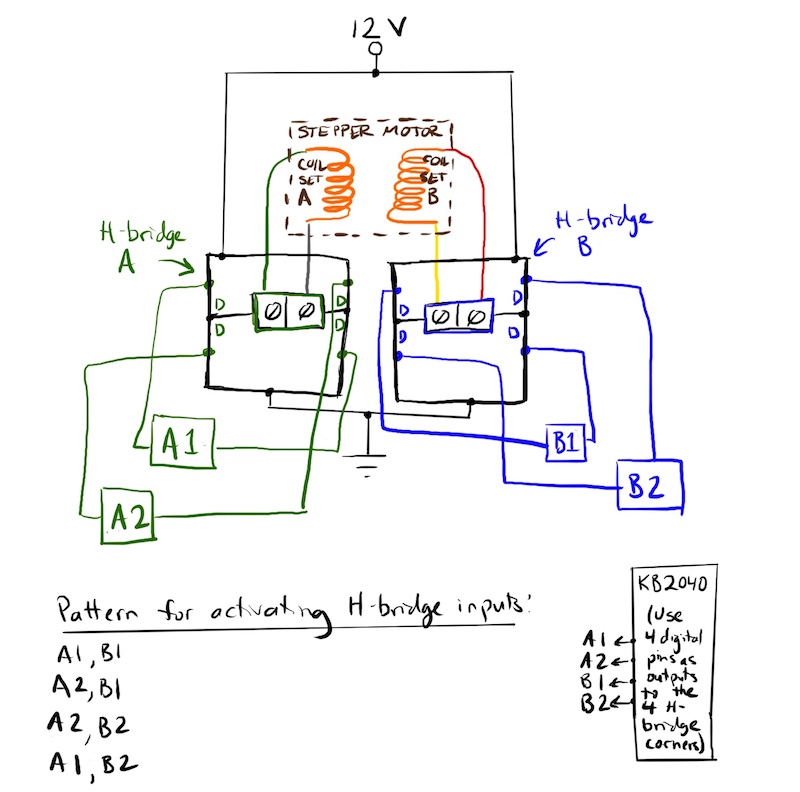
29. Stepper motor set-up (Class 17) #
With one or two partners, set up two working breadboard H-bridges. Choose one KB2040 and one stepper motor to use for this exercise. Hook up each coil of the stepper motor to one H-bridge. Connect one KB2040 digital output pin to each “diagonal” pair of H-bridge corners. You’ll use four KB2040 output pins in total. Control the motor using the code provided here: http://andnowforelectronics.com/notes/kb2040-programming/#stepper-motors
Note that you will need the adafruit_motor library. All CircuitPython libraries for the KB2040 can be downloaded here. Download the entire library bundle to your laptop, and then transfer ONLY the libraries you need to your KB2040.
And here’s what the wiring should look like:
30. More sensors and actuators (Optional) #
-
Potentiometer for input; motor speed for output. Send the voltage output from a potentiometer (knob- or dial-like variable resistor) to an analog input pin on your KB2040. Use that varying voltage to vary the speed of a motor. Extension: Add a button that switches the direction of the motor (you’ll likely need state machine code for this.)
-
Ultrasonic distance sensor for input; motor direction for output. Send the output voltage from a distance sensor to an analog input pin on your KB2040. Use that distance signal to trigger whether your motor spins clockwise or counter clockwise. You get to decide on the distance threshold for switching directions.
-
Pushbutton for input; piezo buzzer for output. Use a pushbutton to send either 3.3 V or 0 V to a digital input pin on your KB2040. Use that button signal to trigger the sound of a buzzer. Power the buzzer with PWM. Explore different frequency and duty cycle values, and see how that changes the sound of the button.
31. Electronics materials: stakeholders & impacts (Class 18) #
See http://andnowforelectronics.com/notes/engineering-ethics-resources/ and worksheet handed out in class.
32. Accessible design reflection (Class 21) #
Think about what kind of person could play your Project 4 game. For example, consider how a disability (e.g., color blindness, other visual impairment, audio impairment) or a specific personal background (e.g., knowledge of a cultural reference) might influence someone’s opportunity to play or their enjoyment of playing. The goal of this exercise is not to prompt you to persuade us that your game is universally accessible. Instead, we are asking you to conduct an honest analysis of the usability of an engineered system by different potential users.
- Who couldn’t play your game as fully as most people?
- Why?
33. Raspberry Pi Flask set-up and challenges (Class 21) #
This Raspberry Pi basics worksheet will help you get familiar with the pins on your Pi. After completing the worksheet, make sure you can complete Raspberry Pi challenges #7, #8, and #9
34. Amplify a strain gauge (Labs following Class 22) #
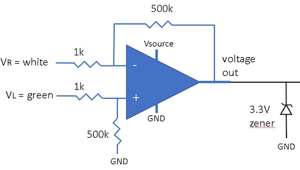
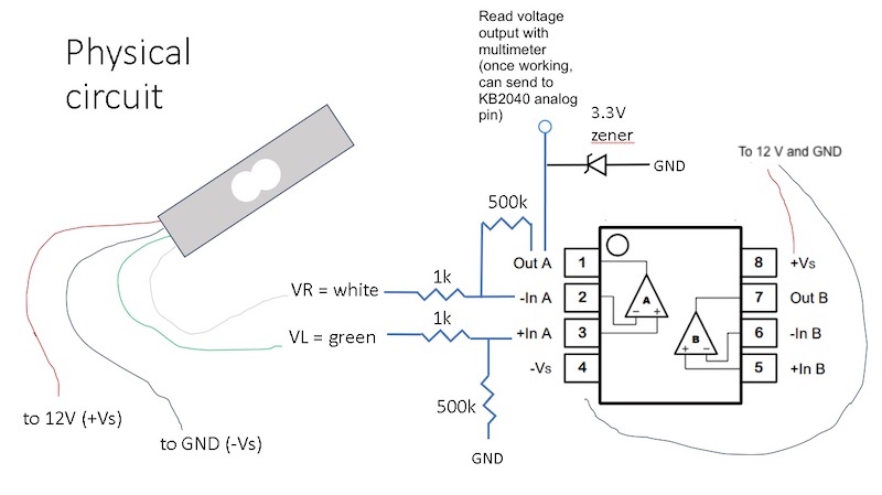
On a breadboard, build a circuit that amplifies the signal from a load cell. Use the differential amplifier circuit shown on the Class 22: Amplification page.
Don’t forget to supply the load cell with 12 V (red lead) and ground (black lead). The green and white leads are the left and right outputs of the Wheatstone bridge circuit.
To be able to plug the load cell leads into a breadboard, you’ll probably need to solder them to jumper wires or crimp them to header pins.
Supplies you’ll need:
- Soldering iron + jumper wires OR crimper + uncrimped pins
- 1 kg load cell from Adafruit (provided in class or lab/Nolop)
- two 500k ohm resistors (provided in lab/Nolop)
- two 1k ohm resistors (from your kit)
- LM 358 op amp (provided in lab/Nolop)
- Zener diode to put in parallel with your V_out from the op amp
- the differential amplifier circuit diagram shown here
After you build the circuit, use your multimeter to measure the op amp’s output voltage, V_out. Clamp one end of the load cell to a table, and press on the other end. If everything is working correctly, you should see the a voltage somewhere between 1 and 3 V that fluctuates with the load you are applying.
35. Project 5 planning, Q & A (Class 22 and 23) #
(a) Discuss these Project 5 planning questions with your team: https://tufts.box.com/s/hlqcn23zkwx6yiuc023vse852xru5tlf
(b) Use this shared doc to post questions about Project 5.
36. Oscilloscopes and PWM signals (Class 23) #
Consider the following Python code, which powers pin 12 on a Raspberry Pi with the pulse-width modulation (PWM) protocol. The goal of this code is to gradually increase the speed of a motor, 2 seconds per speed increment, until it is running at full speed.
import RPi.GPIO as GPIO
import time
GPIO.setmode(GPIO.BOARD)
GPIO.setup(12, GPIO.OUT)

pin12 = GPIO.PWM(12, 500)  # channel=12 frequency=500Hz

    while True:
        pin12.start(0)  # initial duty cycle of 0
        for i in range(0, 11):
            pin12.ChangeDutyCycle(10*i)
            time.sleep(2)
        pin12.stop
Suppose the code doesn’t seem to be making the motor behave as predicted.
You decide to troubleshoot the code by monitoring the signal at pin 12 with an oscilloscope.
An oscilloscope is a tool for measuring electrical signals, like a multimeter, but it keeps a record of voltage and current over time. And it displays that record graphically, on a plot of voltage (or current) vs time. It can detect signals at very small time increments, down to milliseconds. You can explore a virtual version at this oscilloscope simulator.
(1) Let’s say you want to see 5 distinct PWM cycles displayed on the scope window at any given point in time. What should be the settings for (a) time per horizontal division and (b) volts per vertical division?
(2) Sketch what the signal should look like on the scope window when the for loop in the code is at i = 5.
(3) Use the oscilloscope simulator to represent what the signal will look like on the scope at i = 5. You’ll need to adjust both the signal generator (the instrument in the top half of the screen) and the scope settings. https://www.pzdsp.com/elab/virtual_oscilloscope.html