Reference document #
Adafruit KB2040 complete guide
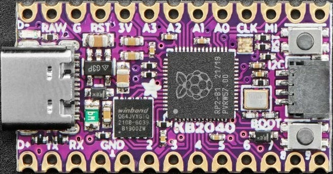
Adafruit KB2040 hardware overview #
Looking at the picture above, you can see 2 large chips, some connectors, and a lot of tiny resistors and capacitors.
The chip just to the right of center is the microcontroller that acts as the brain of the board. It’s an RP2040 chip, which has dual ARM Cortex M0+ cores running at 133 MHz. The 21/19 code on the chip means that this particular chip was manufactured in week 19 of 2021. The RP means that it is made by Raspberry Pi.
The square chip closer to the lower left corner of the board is the Flash memory chip for storing files and code.
Adafruit provides a handy overview of all the KB2040 components and pins.
Why are there no header pins? #
The KB2040 is shipped without header pins to keep costs low and to give users options for how they attach sensors and actuators to it. Users can decide whether and which header pins to solder to the PCB.
In ME 30, you’ll want to be able to plug your KB2040 into a breadboard for stability and wiring. Find the header pins in the ziploc bag in your ME 30 box, and solder them onto the KB2040 PCB. Before you do this, check out Adafruit’s soldering tutorial.
Connectors #
The board has two different connectors. On the left of the board is a USB-C connector used for power and/or data. You’ll connect to your computer through USB-C to install CircuitPython on your KB2040 and to edit code. On the right edge of the board is a STEMMA QT connector, which allows you to connect I2C sensors and breakout boards to the KB2040.
Buttons #
You’ll notice two small black buttons encased in silver boxes. The RST (reset) button resets the board without disconnecting it from power. The BOOT (boot select) button is used when you install or update CircuitPython on your KB2040 (press and hold BOOTSEL while plugging the board into USB or pressing RESET). This button is also usable as an input in CircuitPython code, on pin «board.BUTTON».
LEDs #
The KB2040 has two built-in LEDs.
The one above the USB-C connector is the green power LED that indicates whether the board is receiving adequate power.
- green blink = code finished; no error
- red blink = code ended due to Python error
- yellow blink = safe mode; no user code run; check serial monitor
The NeoPixel LED to the left of the RESET (RST) button can be programmed to glow in different colors using the variable board.NEOPIXEL and the code in the NeoPixel library.
Current Limits #
The KB2040 has two current limits you should be aware of.
- The default current limit per pin is 4 mA. Note that 3V divided by 100 ohms draws a current of 30 mA, which is more than 4 mA.
- The total current limit across all pins is 50 mA.
- For more info on the current limit per pin, search the RP2040 datasheet for “drive strength.”
Learning to program your KB2040 #
In ME 30 you’ll install CircuitPython on your KB2040 so that it can run Python programs. We’ll use these CircuitPython set-up instructions provided by Adafruit.
Adafruit’s more general CircuitPython Tutorials are a great resource for newcomers to the world of microcontrollers.