Sensor amplification #
Sensors produce real small voltages, so we need to amplify them.
Strain gauges #
A strain gauge is a small wire that changes resistance when it is stretched. The strain gauges we’ll use in ME 30 are made of constantan, an alloy of copper and nickel. The constantan is attached in a serpentine shape to a polyimide film. The 14 sections in the serpentine shape means that the wire behaves like 14 resistors in series, each of which increases in resistance when stretched and decreases in resistance when compressed. A typical strain gauge has a total baseline resistance somewhere between 100 and 1000 Ω. That value changes by a few ohms when the wire changes in length.
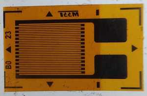 Photo credit: Pleriche - Own work, CC BY-SA 4.0
A strain gauge’s “GF,” or gauge factor, is the ratio of fractional change in electrical resistance to the fractional change in length (strain). A GF of 2 is typical for strain gauges made of tiny metal wire, like ours. If we could measure the gauge’s resistance change directly, we could use the GF to easily compute the value of the strain. However, for a sensor circuit to be detectable by a microcontroller (like an Arduino or KB2040), the sensor’s output needs to be a voltage value, not a resistance. How can we convert a resistance change into a voltage measurement? Remember voltage dividers?
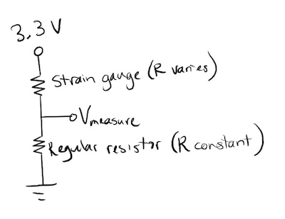
If we put the strain gauge in series with a normal resistor (of the same number of ohms) to make a voltage divider supplied with 3.3 V, the voltage between the two resistors will be around 1.65 V. The voltage will go up and down in proportion to strain, so we could use that voltage value as our signal. The problem, however, is that the voltage change is so small that it will be hard to detect.
Amplification #
The solution is to combine two classic circuits: a Wheatstone bridge and a differential amplifier.
Wheatstone bridge: Using voltage measurements to determine resistance change #
A Wheatstone bridge (invented in 1833 by Samuel H. Christie; Wheatstone just blathered on about it) is a network of four resistors - at least one of which has an unknown resistance value that you’d like to know. The idea for our strain gauge is to add a second pair of resistors in parallel with the original voltage divider and then measure the voltage difference between the two central nodes. It’s like our voltage is a bridge across the middle of the circuit.
In the strain sensor we are using in ME 30, there are four strain gauges arranged in a Wheatstone bridge. Two of the resistors are placed on the bottom of a short beam and two are placed on the top of the same beam. This whole apparatus is called a load cell.
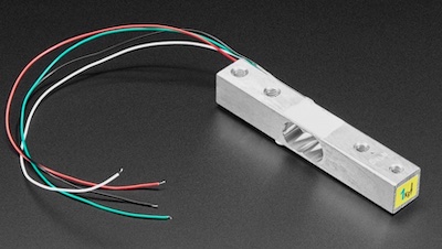 Photo credit: Adafruit
The Wheatstone bridge in our load cell has two major advantages.
-
Because we are comparing two voltages that change in opposite directions, we get twice the signal we would get without a bridge. Having strain gauges in compression and tension simultaneously doubles our signal again, so our signal is 4 times bigger than it would be in the single strain gauge example above.
-
Resistors change resistance when they heat up, which means that your sensor signal will slowly drift with the temperature in the room, and it gets worse because the current running through the resistors heats them up even more. When comparing the two sides of the bridge, they are both at roughly the same temperature, so the temperature drift is the same on both sides, which means it cancels out in the difference.
How the circuit works in detail #
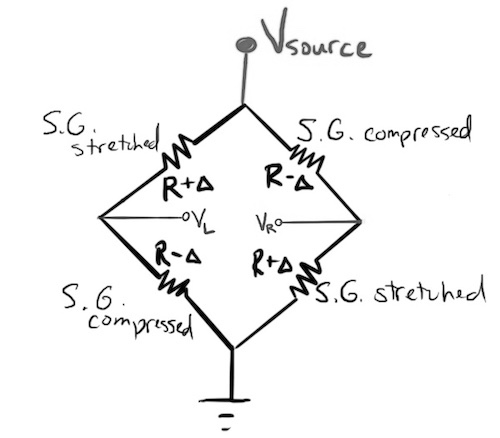
All four strain gauges have the same baseline resistance, R. That’s their resistance when not strained. When the load cell is unloaded, all the resistance values equal, so VL is equal to VR, and the voltage difference across the “bridge” is 0. However, when the beam is bent, all the gauges change in length. Based on their placement on the beam, two of the gauges stretch, and they increase in resistance by delta. The other two gauges compress, and they decrease in resistance by delta. Now VL and VR differ from each other. That means the “bridge voltage,” VL - VR, will be nonzero.
How does that bridge voltage relate to the resistance change (delta) caused by the strain?
We can use the voltage divider principle to find out.
\[\begin{aligned} V_{source} &= \text{source voltage (12 V for our circuit)}\\ R &= \text{baseline resistance of strain gauge}\\ \Delta &= \text{change in resistance of gauge due to strain}\\ V_{L} &= \text{voltage relative to ground on the left side of the bridge}\\ V_{R} &= \text{voltage relative to ground on the right side of the bridge}\\ V_{bridge} &= \text{voltage across the outputs of the bridge}\\ \end{aligned}\] \[\begin{aligned} V_{L} &= \frac{R + \Delta}{(R + \Delta) + (R - \Delta)} * V_{source}\\ V_{R} &= \frac{R - \Delta}{(R - \Delta) + (R + \Delta)} * V_{source}\\ V_{L} &= \frac{R + \Delta}{2R} * V_{source}\\ V_{R} &= \frac{R - \Delta}{2R} * V_{source}\\ V_{bridge} &= V_{L} - V_{R} = \frac{(R + \Delta) - (R - \Delta)}{2R} * V_{source}\\ V_{bridge} &= \frac{2\Delta}{2R} * V_{source}\\ \frac{V_{bridge}}{V_{source}} &= \frac{\Delta}{R}\\ \end{aligned}\]So that’s how the circuit will give us a voltage proportional to strain, but we still have a problem, which is that the voltage generated is very, very small.
Strain usually occurs in quantities of millistrain or microstrain, something like 0.0005ε, which is 0.5 millistrain(mε) or 500 microstrain (µε). Let’s take a piece of metal that experiences a strain of 500µε, or 0.0005ε. With a gauge factor of 2, the change in resistance will be only twice that: 0.001, or 0.1%!
If the baseline resistance of the gauge is 1000 Ω, its resistance change at 500µε would be only 1 Ω. The bridge voltage produced by that resistance change would be 0.012 V, not easily detected by our microcontrollers. We need a device that can take a very small bridge voltage and amplify it into a voltage we can measure accurately.
Differential amplifier: Using an op amp with negative feedback to amplify a voltage difference #
To make the signal bigger, we’ll build a differential amplifier. You can buy a strain gauge amplifier like the HX711, but we’re going to build one from scratch using a chip called an operational amplifier, or op-amp.
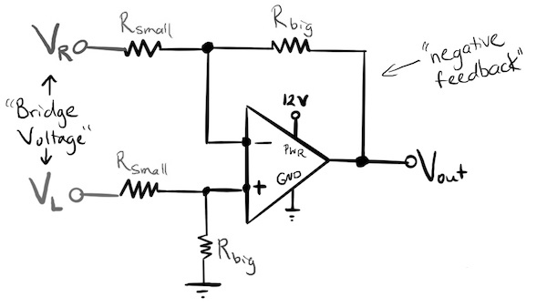
The golden rules of op amps #
If you have set up your op amp properly, it will obey these two rules:
- No current flows in or out of its inputs, V1 and V2
- The op amp adjusts its output voltage to make the voltages at V1 and V2 equal to each other.
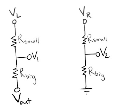
We can represent the circuit above as two voltage dividers.
We’ll use the LM358 op-amp, which has the pin-out shown below. It includes two op-amps, but we’ll just use one of them.
- The IN1- and IN1+ pins are the points labeled “-” and “+” in the op-amp schematic symbol above. Those are the pins where the strain gauges’ Wheatstone bridge outputs come in (through the small resistors).
- The OUT1 pin is the same as Vout.
- V+ and V- are where you connect 12 V and ground.
- To get the signal from the Adafruit load cell to be detectable within the KB2040’s input range of 0 to 3.3 V, we want our amplifier circuit to provide a gain of 500. So use Rbig = 500k Ω and Rbig = 1k Ω.
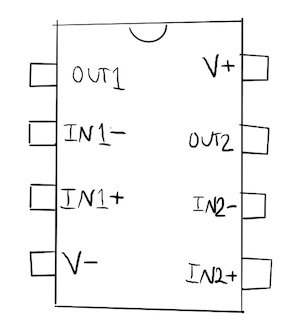
Diagram of the entire circuit #
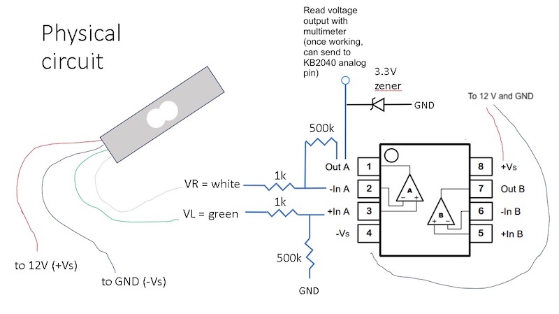
After you build the circuit, use your multimeter to measure the op amp’s output voltage, V_out. Clamp one end of the load cell to a table, and press on the end labeled with the “1 kg” sticker. If everything is working correctly, you should see the voltage somewhere between 70 mV and 3.3 V, fluctuating with the force you are applying to the load cell.
The reason the output maxes out at 3.3 V, even if you press very forcefully on the load cell, is the Zener diode, which (when wired in the reverse-bias direction, as shown here) shunts off extra voltage beyond 3.3 V.