Digital input #
If you indicate in your microcontroller code that a digital pin is functioning as an input, its value will be a logical (binary) variable. The microcontroller will detect the voltage at the pin and label it as either True or False. Voltages above 2 V are interpreted as True, and voltages below 1 V are interpreted as False. In between 1 V and 2 V is a transition state where the pin state can’t be guaranteed.
When you set a pin to be an input, you can also refer to it as a sink. When it’s set up to be an output, it’s a source (of current).
Push button for digital input #
Here’s how you can set up a push button to toggle the value of a digital pin between True and False. The pin must be set up in the code as INPUT.
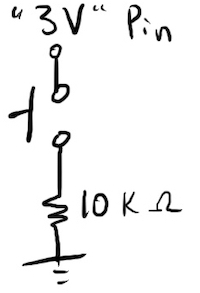
If combined with the circuit shown above, this Circuit Python code will print 1 (True) when the button is pressed and 0 (False) when not pressed.
import digitalio
import time
import board

button = digitalio.DigitalInOut(board.D6)
button.direction = digitalio.Direction.INPUT

while True:
    print(button.value)
    time.sleep(0.1)
Analog input #
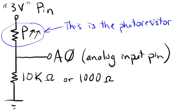
The analog pins on a microcontroller are able to detect a range of voltages between 0 and 3.3 V and store the pin value as a continuous variable, rather than simply labeling the pin as True or False.
This Circuit Python code will print the value of analog pin A0. The pin values will range from 0 (indicating 0 V detected at the pin) to 65535 (indicating 3.3 V detected at the pin).
import time
import board
import analogio

inputvoltage = analogio.AnalogIn(board.A0)

while True:
    print((inputvoltage.value,))
    time.sleep(0.1)
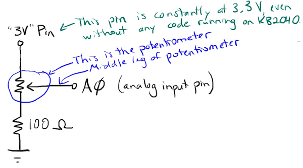
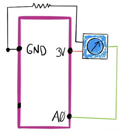
Potentiometer as a rotation sensor #
Photoresistor as a light sensor #